IRDAR — a Scanning Infrared Rangefinder
IRDAR ("IR radar") is a scanning infrared rangefinder built on a Freescale MC9S08QE128 (HCS08 8-bit). A servo pans a pair of Sharp infrared distance sensors through a full circle while the microcontroller streams angle and range to a Processing sketch that draws a radar-style sweep.
Step 1Define
How It Works
- A servo continuously pans a bracket carrying two Sharp IR distance sensors mounted back-to-back, so between them they see all the way around.
- An encoder on the servo shaft tracks the angle; a slip ring carries the sensor wires through the rotating joint.
- The microcontroller samples both sensors, pairs each reading with the current angle and direction, and sends a short frame over serial.
- The Processing sketch converts each reading to centimetres, places it at the right angle, and paints it on a green radar display with range rings.
Step 3Build
Hardware
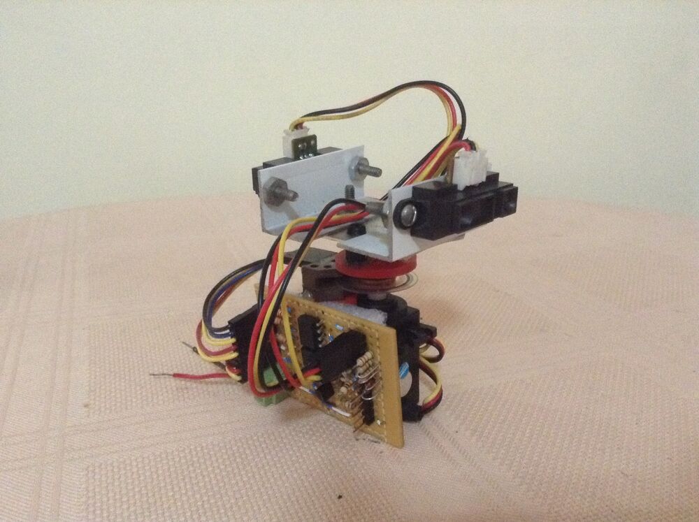
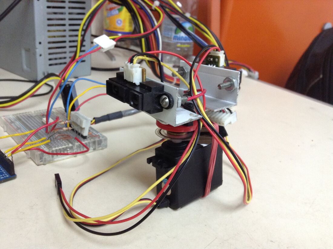
The assembled scanning head — servo, slip-ring joint, sensor bracket and signal board.
| Microcontroller | Freescale MC9S08QE128 (HCS08, 8-bit) on a DEMOQE128 board; ~4.2 MHz internal bus clock |
| Scan drive | Continuous-rotation servo on a 50 Hz PWM (TPM1), swept by ramping the pulse width 500–2500 µs |
| Angle feedback | Shaft encoder into a keyboard-interrupt (KBI) pin, counted in firmware |
| Sensors | 2 × Sharp analog IR distance sensors, back-to-back, read on ADC channels 0 and 1 |
| Link | Asynchronous serial (SCI) to the PC at 9600 baud |
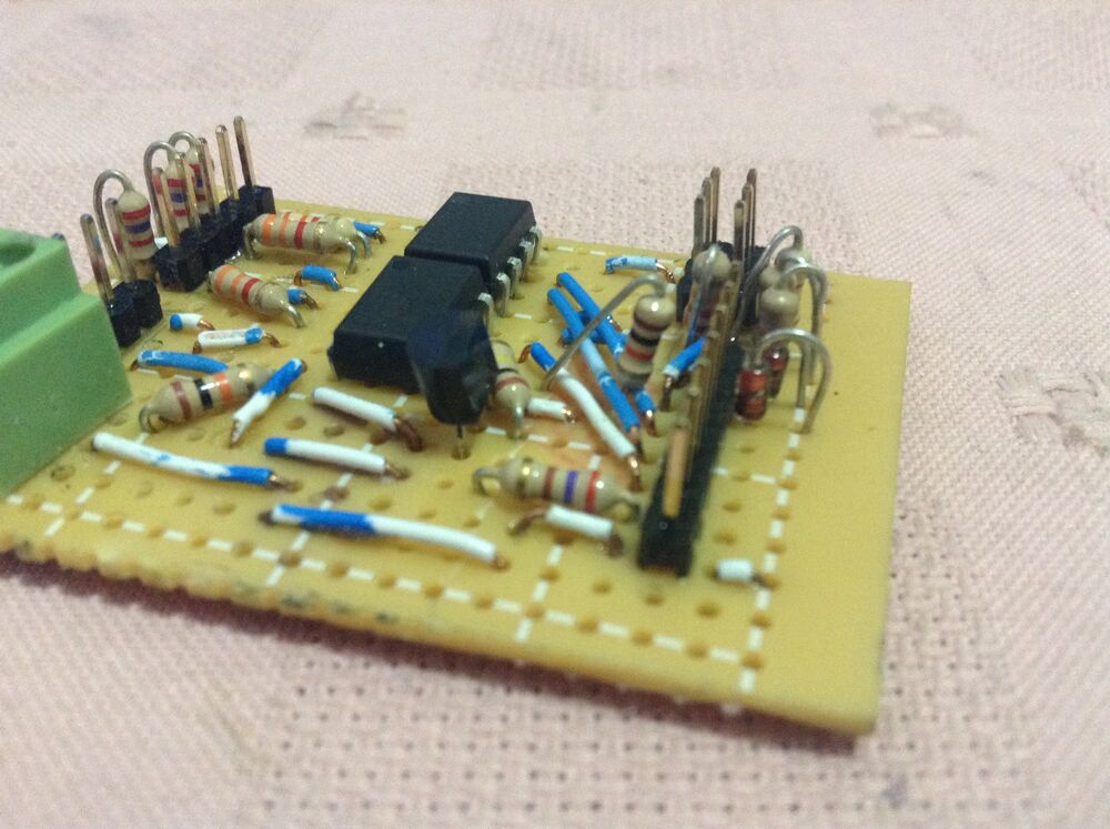
| Extras | Slip ring for continuous rotation; a hand-wired board for sensor and encoder signal conditioning |
Firmware
Written in CodeWarrior for HCS08 with Processor Expert generating the peripheral drivers. The work splits between three interrupts and a small state machine:
- Servo sweep — a timer interrupt ramps the servo pulse width by a fixed step each tick and flips direction at the 500 / 2500 µs limits, so the head oscillates across the scan arc.
- Encoder count — the KBI interrupt increments an angle counter on every encoder edge. It is kept as two bytes (rolling the low byte at 124) so it survives the byte-oriented serial link.
- Measurement tick — a timer interrupt nudges the main loop from
WAITintoMEASURE.
The main loop then runs MEASURE → SEND → WAIT: read both ADC channels, then transmit one framed packet —
'C'  count_hi  count_lo     encoder counts
'D'  direction               sweep direction
'A'  sharp1  sharp2          the two ADC readings
'E'                          end of frame
The Radar Display
The Processing sketch (in GUI/) opens the serial port, parses each frame and:
- rebuilds the sweep angle from the encoder count and direction (about 230 counts across the ~180° arc);
- converts each raw ADC value to centimetres with a per-sensor exponential fit of the Sharp response — e.g.
distance = 89.41 · e^(-0.04 · adc) + 6.41— the curves fitted inEcuaciones sharps.xlsx; - plots the two sensors 180° apart, so one sweep of the servo fills the whole circle;
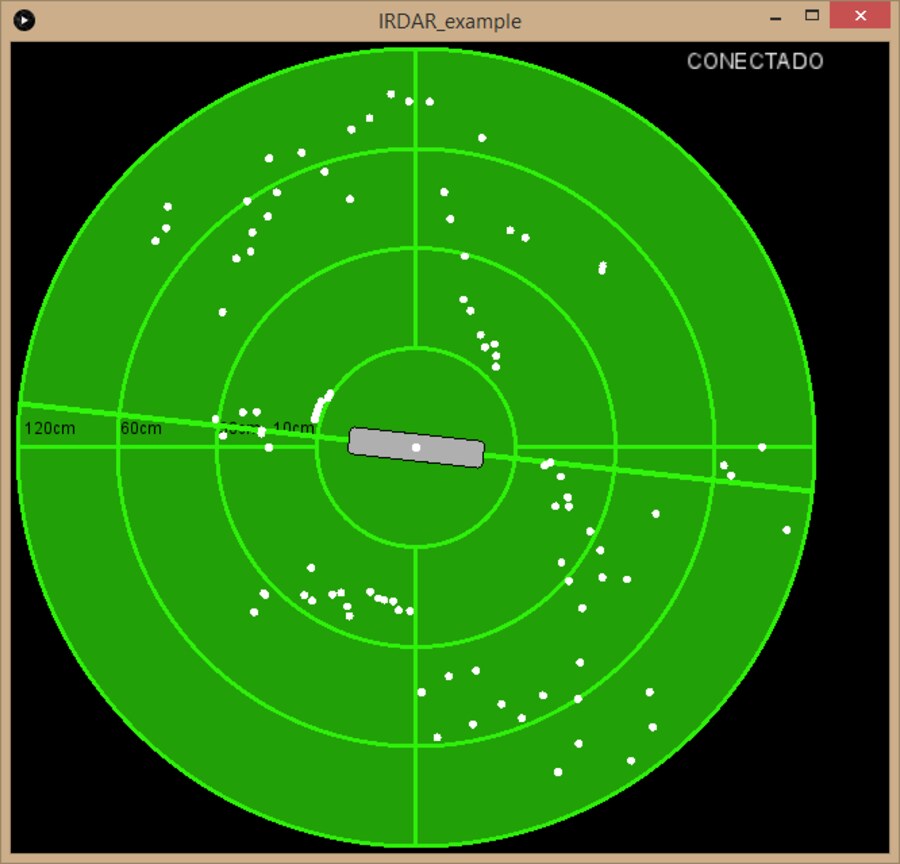
- draws it all on a green scope-style display with range rings at 10, 30, 60 and 120 cm and a rotating sweep bar.
Step 4Test
Sensor Calibration
Each Sharp was calibrated on its own, read through the DEMOQE board and the signal board: Ecuaciones sharps.xlsx holds one reading per centimetre from 1 to 50 cm for each sensor. Both curves peak at 100 counts around 5–6 cm and fall away on both sides, so very close objects are ambiguous — sensor 1 reads 69 at 1 cm and 70 at 12 cm — and the spreadsheet charts distance against reading only from 5 cm out. The two sensors don't read alike (22 against 26 counts at 40 cm), which is why the display gives each its own curve: 89.41 · e^(-0.04 · adc) + 6.41 for sensor 1 and 105.27 · e^(-0.04 · adc) + 6.36 for sensor 2.
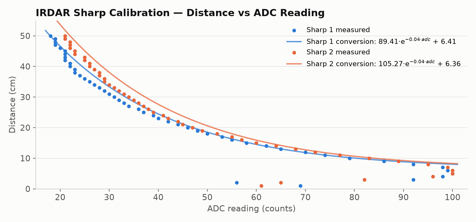
Distance against ADC reading for both sensors, one point per centimetre from 1 to 50 cm, with the conversion curves the radar display uses. The stray points along the bottom are the 1–4 cm readings, below the peak.
Plotted against the measurements, both conversions land within about half a centimetre from 9 to 14 cm, and read about 2 to 4 cm long between roughly 27 and 42 cm.
Running Live
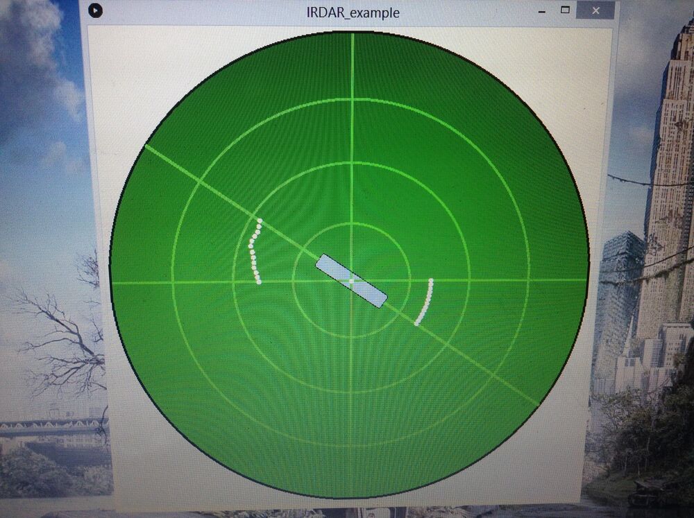
The display running live, with obstacle points picked up on both sides of the sweep.
Notes
- Built on the HCS08 / CodeWarrior / Processor Expert toolchain, all now legacy — the design ideas carry over to any small MCU with a timer, an ADC and a UART.
- The serial frame is parsed by fixed byte position, so a sensor or count byte that happens to equal a delimiter letter can misalign it; a length-prefixed or escaped framing would be more robust.
- The two-Sharp / 180°-offset trick trades a full second sensor for full-circle coverage from a half-circle sweep — neat, but the two sensors need matched calibration.
Posted In:
Embedded Software