LoRa Development Board | RFM95W-915S2
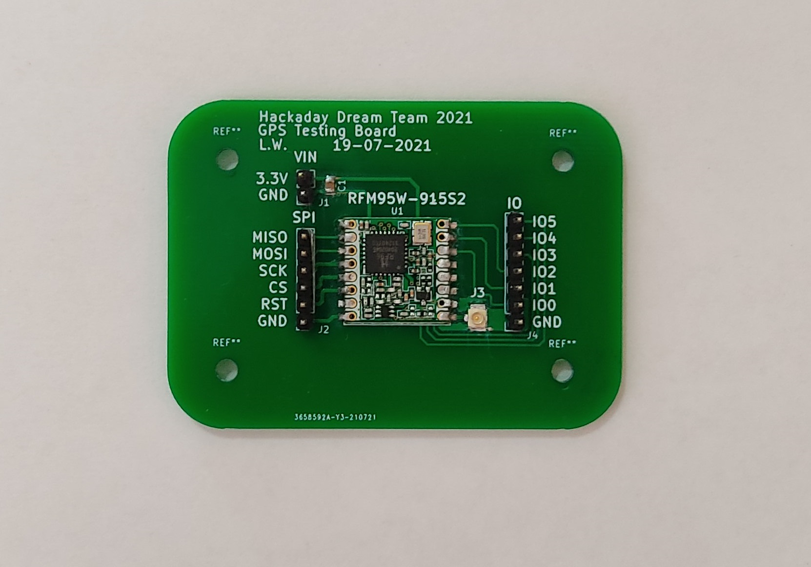
The RFM95W-915S2 Development board is a PCB that contains a RFM95W LoRa transceiver, a U.FL connector for the external antenna, a decoupling capacitor and a group of headers connected to the different pins of the transceiver. The transceiver can be used as a sender or a receiver.
Schematic
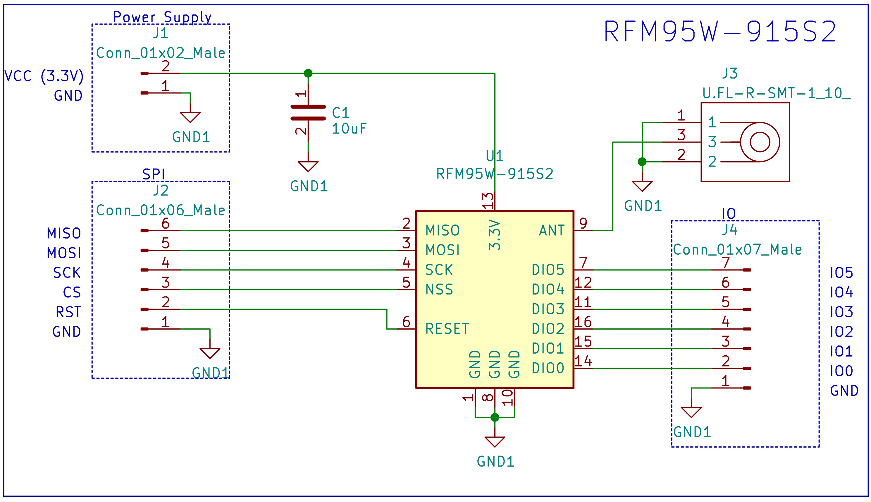
Schematic of the LoRa Development Board.
Bill of Materials
PCB
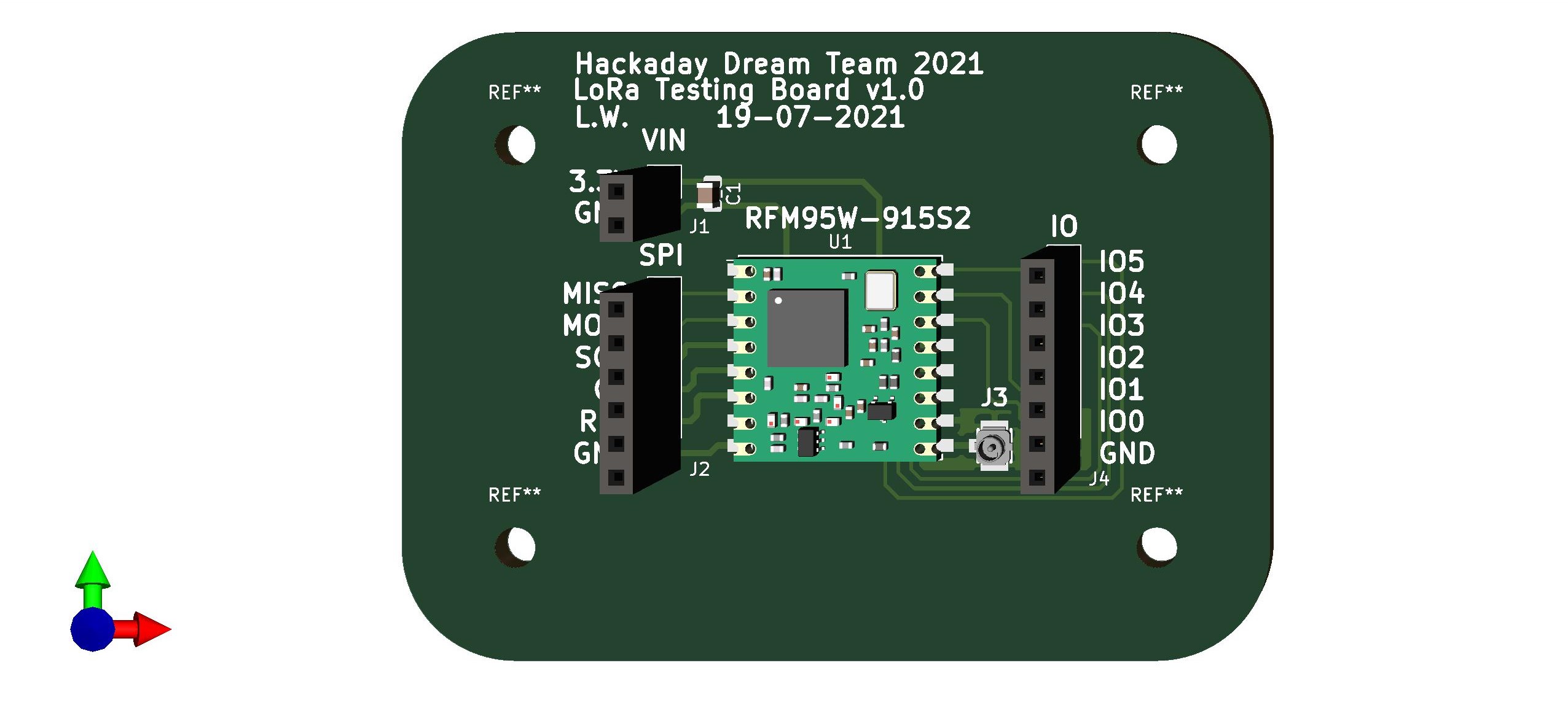
3D Model of the LoRa Development Board.
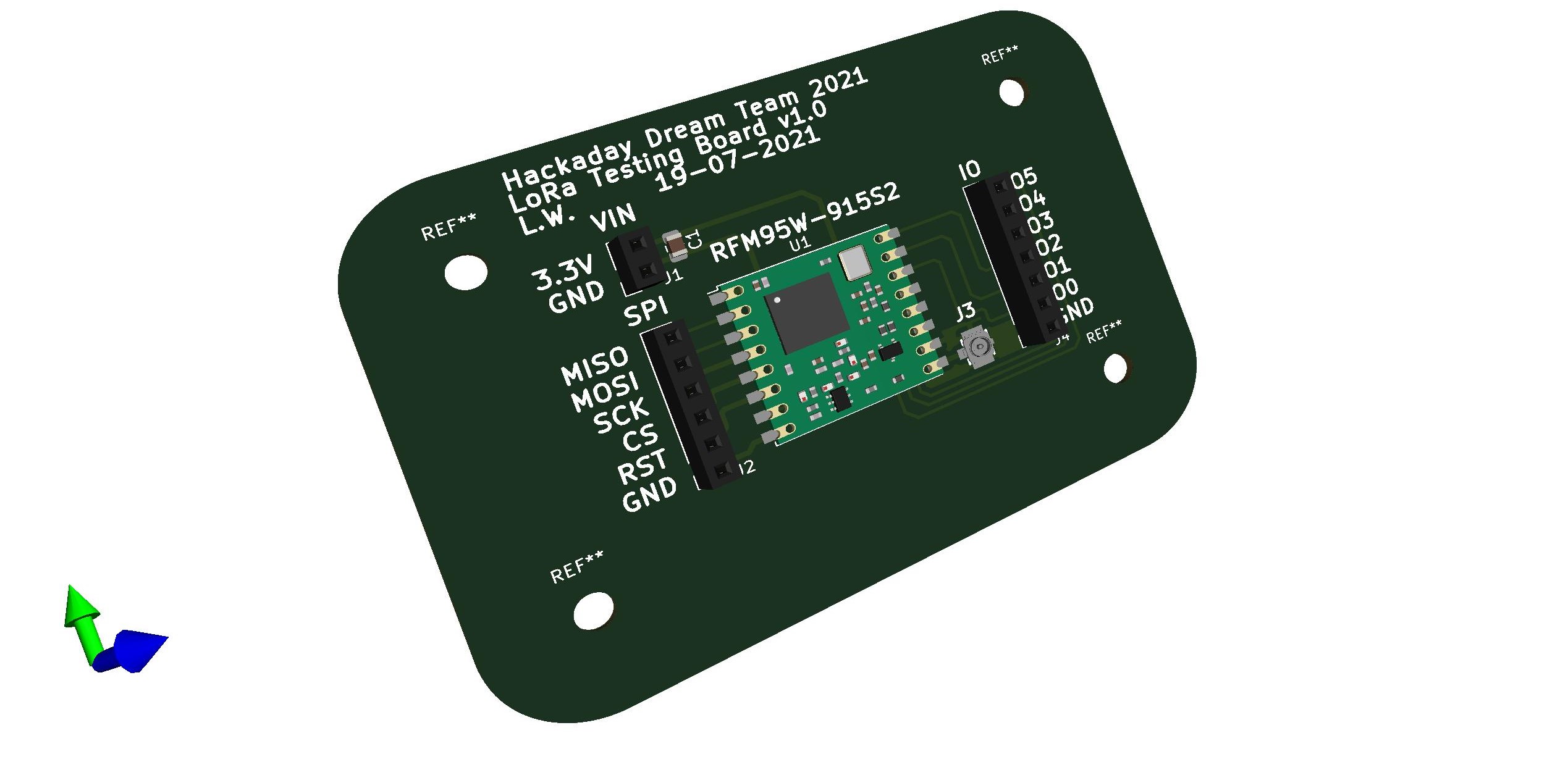
3D Model of the LoRa Development Board.
Firmware and Testing
The webpage randomnerdtutorials.com has an amazing tutorial named ESP32 with LoRa using Arduino IDE – Getting Started, that tutorial contains detailed information about how to use the RFM95 with an ESP32 (the same microcontroller that was selected for our designs). I used the same firmware and connections provided by the tutorial.
The test requires 2 transceivers, one of them will be used as a sender and the other as a receiver. In this case, one of the transceivers is the RFM95W-915S2 Development board and the other one is the RFM95W transceiver from Adafruit.
The connections are the following:
| ESP32 | RFM95W-915S2 Development Board |
|---|---|
| 3V3 | 3.3V |
| GND | GND |
| GPIO 14 | RST |
| GPIO 5 | CS |
| GPIO 18 | SCK |
| GPIO 23 | MOSI |
| GPIO 19 | MISO |
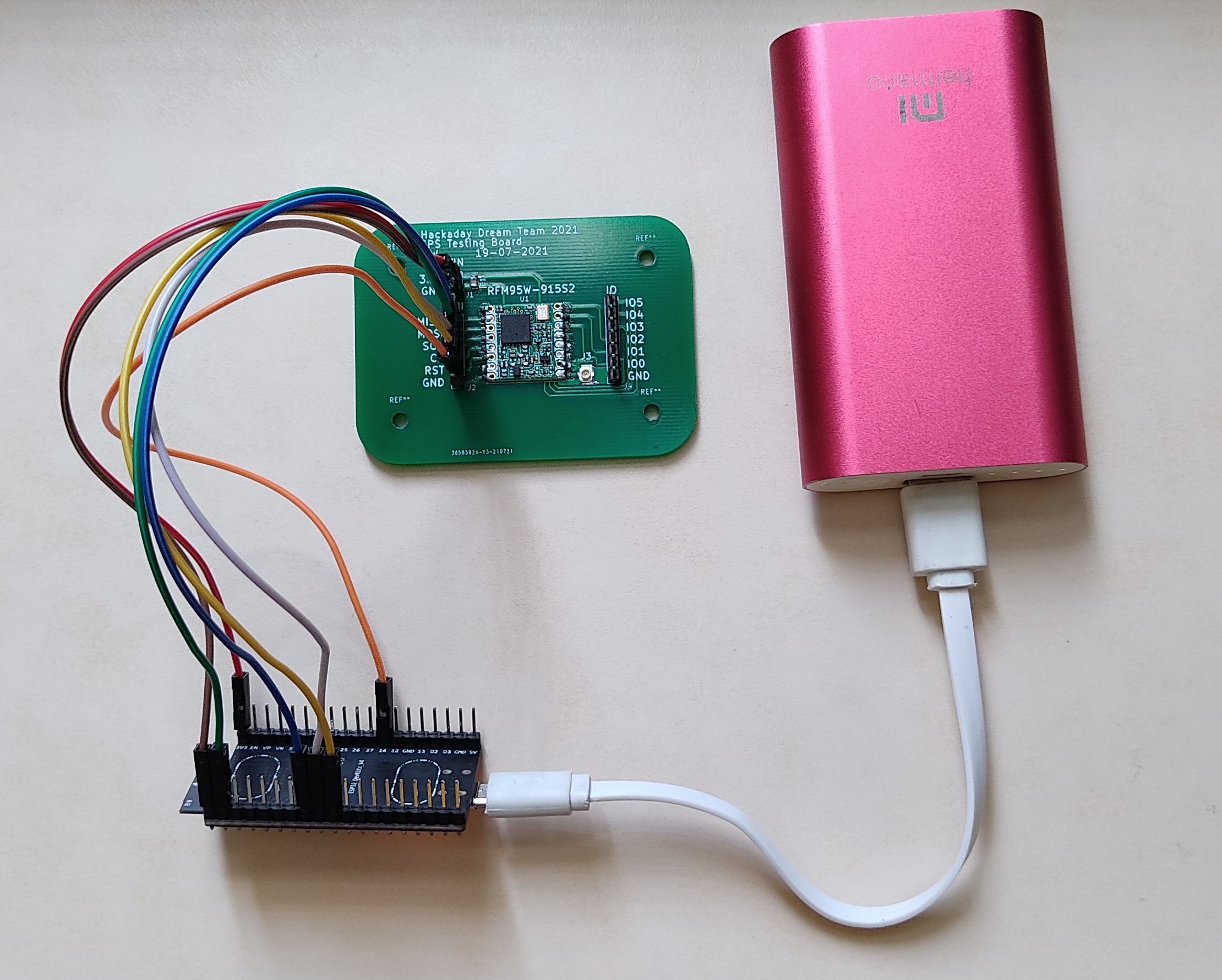
Custom LoRa Dev Board and ESP32 used in the test.
| ESP32 | RFM95W Board from Adafruit |
|---|---|
| 3V3 | VIN |
| GND | GND |
| GPIO 14 | RST |
| GPIO 5 | CS |
| GPIO 18 | SCK |
| GPIO 23 | MOSI |
| GPIO 19 | MISO |
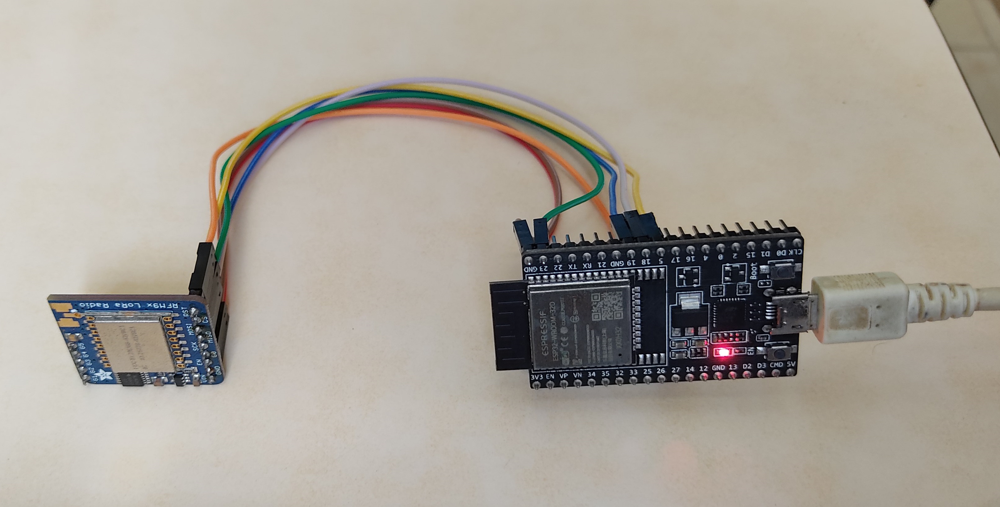
RFM95W transceiver from Adafruit and ESP32 used in the test.
This repository contains a folder named /Firmware/ that contains the project for the transceiver as a receiver and a sender.
Both of the RFM95W Boards were used as a sender and receiver, the result was successful in both cases. During the test, one of the transceivers sends the package "hello counter", where the counter is a number that goes from 0 to 32767. The other transceiver receives the package and prints the message through serial.
Requisites
Results visualized in the serial monitor from the receiver circuit:
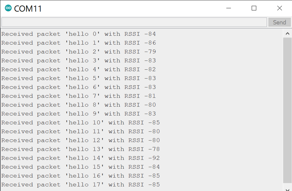
Results from the test.
For more information about the firmware visit the original tutorial for the RFM95W.
Posted In:
Embedded Hardware