
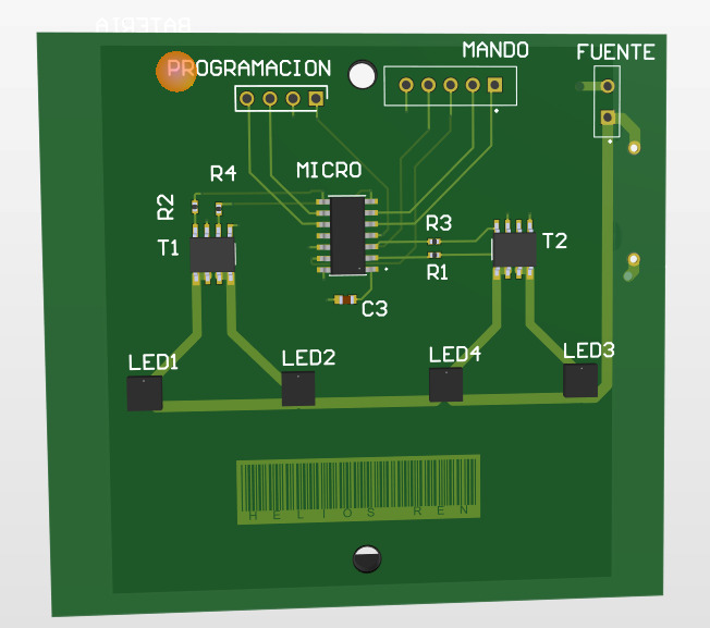
HELIOS REN Tail Light System
This project presents the design stages of a prototype tail-light system for a bicycle. Components were selected to match the project requirements and our team’s criteria. The system’s operation was simulated in Proteus and the firmware was written with MPLAB X. The circuit’s PCB design and the changes made to the competition brief are also presented.
Step 1Define
Requirements
General requirements
Design a prototype of a tail-light system for bicycles.
Specific requirements
- 25 hours of autonomy in continuous operation.
- Rechargeable batteries, recharged through a USB port.
- Three operating modes.
- A market-viable final price (25 € < price < 40 €).
- Use components that are available, affordable and supported on the market.
A PRO version of the product is also proposed, with these additional requirements:
- Cornering lights on each side, plus turn indicators.
- A handlebar-mounted remote to control the product’s behaviour.
Figure 1 describes the operating modes proposed for the tail-light system. It also shows the use of a single button to move between modes. The cornering lights are not part of the operating modes; they have only two states: on and off.
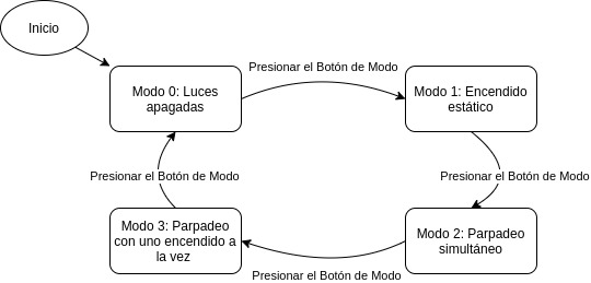
Figure 1: diagram of the tail-light operating modes.
Step 2Simulate
Battery Sizing
The battery bank was sized for 26 hours of continuous operation with both main lights at full power, leaving margin over the 25-hour requirement. Each LED draws up to 180 mA, so: 2 × 180 mA × 26 h = 9360 mAh. Four 2600 mAh cells were connected in parallel, giving 10 400 mAh — enough to cover the LED demand described above.
Proteus Simulation
The proposed circuit was simulated in Proteus; Figure 2 shows the design. The remote’s switches were modelled as switches, and a button was added to control the modes. The power supply is not shown in the simulation; only voltage sources of the corresponding value are included. The BTS3405GXUMA1 devices used as transistors cannot be simulated in Proteus, so they were represented by their MOSFET equivalents. The different operating modes were simulated successfully; the delivered video shows them working.
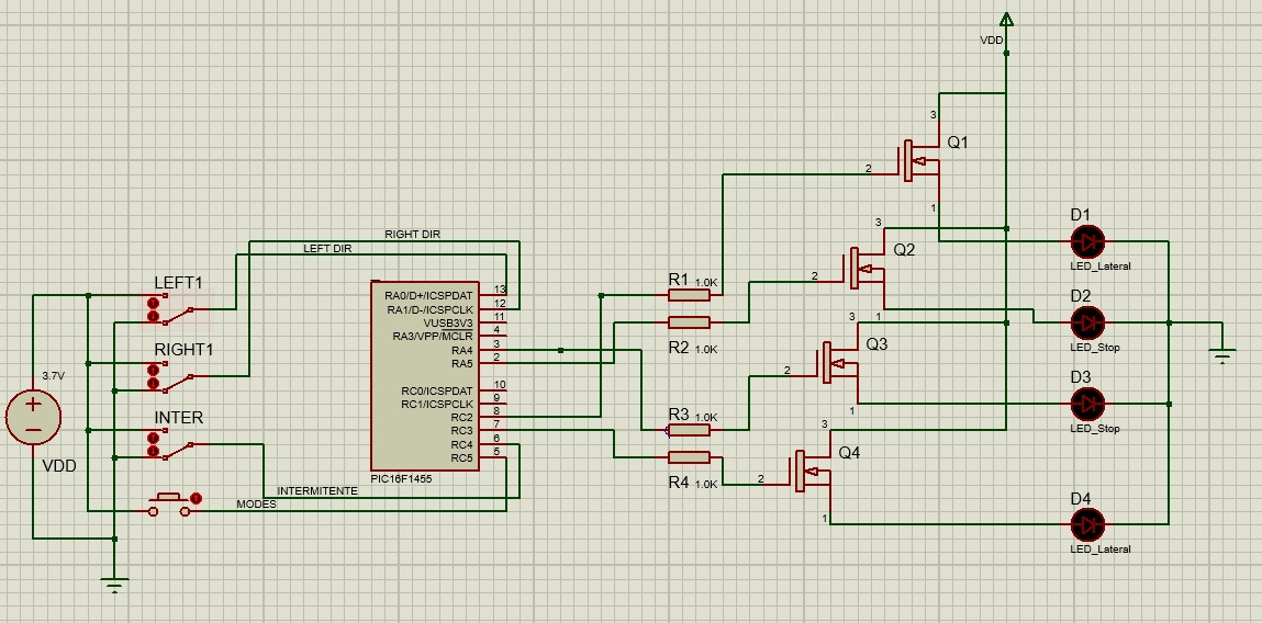
Figure 2: circuit model in Proteus.
Step 3Build
Hardware
Figure 3 shows the hardware block diagram of the prototype. It includes the essential parts of the design: push-buttons, batteries, battery charger, lights, and the transistors that make up the power-control stage of each LED. In Figure 3, the rear lights that are not used to signal turns are called brake lights.
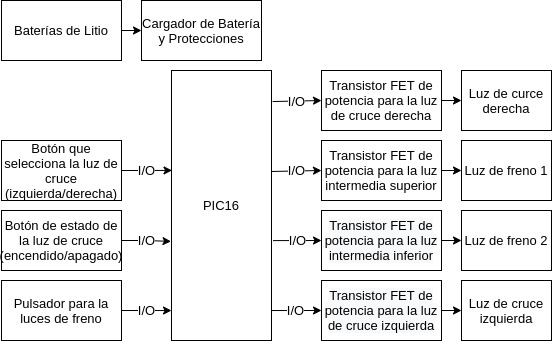
Figure 3: hardware block diagram.
Power supply
To use rechargeable lithium batteries, a module based on the TP4056 IC was chosen; it provides constant-current / constant-voltage charging for single-cell lithium-ion batteries (Figure 4). A single cell has a nominal voltage of 3.7 V, which is used as the supply voltage for the logic circuits in the design.
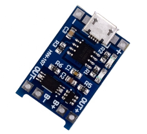
Figure 4: TP4056 battery-charger module.
Microcontroller
The project’s functional requirements are:
- 4 digital outputs to drive 4 LEDs.
- In-circuit serial programming (ICSP).
- 3.7 V supply.
- 4 digital inputs to control the behaviour of the LEDs.
The main constraint when choosing a microcontroller for this application is the number of digital I/O pins, so the search focused on a device that met that need while being conservative with internal resources. The PIC12F and PIC16F families have an 8-bit CPU running at up to 5 MIPS (millions of instructions per second); PIC12F devices have 8 pins, while PIC16F devices come in 14- to 64-pin packages. The Microchip PIC16F1454 was chosen as the family closest to meeting the functional requirements.
The PIC16F1454/1455/1459 family is based on the mid-range core with 49 instructions and delivers up to 12 MIPS, 14 KB of program memory and 1024 bytes of RAM. The board uses the configurable internal oscillator, which is accurate to ±0.25 %.
Key features of the PIC16F1455:
- CPU speed up to 48 MHz.
- 16 MHz internal oscillator block, selectable from 16 MHz down to 32 kHz.
- 12 I/O pins (PIC16F1454/1455).
- In-circuit serial programming (ICSP).
- Two 8-bit timers.
The device also has a 10-bit, 5-channel ADC and an MSSP with SPI and I2C, none of which are used here. The pinout is shown in Figure 5.

Figure 5: PIC16F1455 pinout.
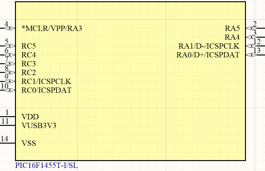
Figure 6: PIC16F1455 schematic symbol.
The microcontroller can be programmed with an ICSP programmer (usable with any PIC chip). The ICSP connections are shown in Figure 7.
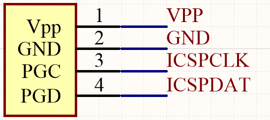
Figure 7: ICSP header on the schematic.
An external oscillator was not considered necessary, for two reasons:
- The microcontroller has an accurate, configurable 16 MHz internal oscillator.
- Although timing errors are possible, this application is not sensitive to millisecond-level changes: the light modes are measured in seconds, so any change in behaviour would be practically imperceptible and would not justify the added hardware complexity.
- An external device would use 2 more GPIO pins for this purpose.
Lighting
Four 0.5 W LEDs were used: two for the brake lights and two for the cornering lights. The white LED OVS5MWBCR4 from TT Electronics (50 lm) was selected; its forward voltage is in the [3.0 ; 4.1] V range, with a nominal current of 180 mA and a peak current of 350 mA. No current-limiting resistor is needed for these LEDs because the supply is 3.7 V. A 10° focusing lens is fitted to each LED to improve viewing distance.
Four transistors are needed to drive the LEDs. Two Infineon BTS3405GXUMA1 devices were chosen, each containing two transistors with a maximum drain-source voltage (VDS) of 42 V, a maximum drain current of 350 mA each (ideal for the chosen LEDs) and a 1.7 V turn-on voltage, making them compatible with the microcontroller’s 3.3 V logic.
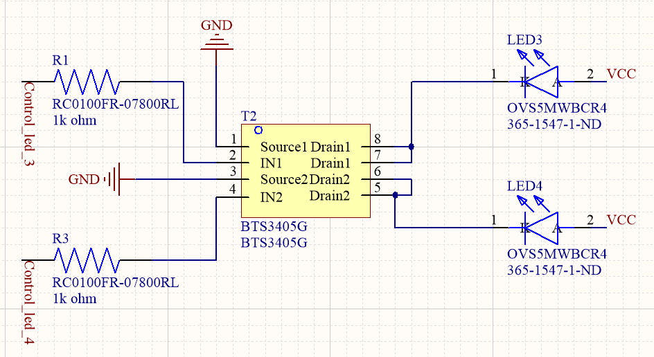
Figure 8: LED control system.
Control interface
The lights can be controlled in two ways. The first uses a single button that cycles through the operating modes and back to off. This button is on the device enclosure.
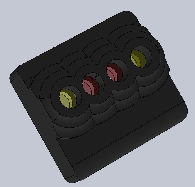
Figure 9: single-button control on the enclosure.
The second uses a remote control. This option adds features such as turn indicators and cornering lights, while the operating modes stay the same. This version of the product has an extra cost and is shown below.
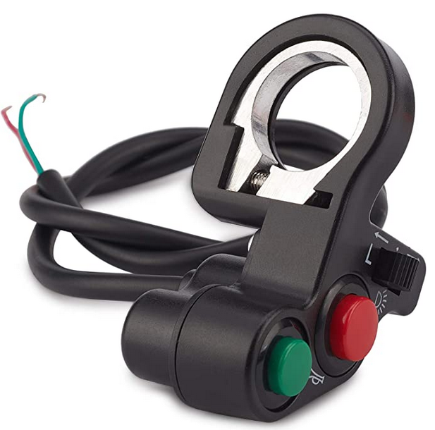
Figure 10: external control for the LED lights.
Software
Figure 11 shows the software block diagram for the microcontroller. Each push-button is connected to an I/O port configured as an input. The microcontroller reads the state of each input and handles any switch bounce.
A slider selects which cornering light is used. A button puts both cornering lights into blinking mode. A push-button changes the state of the rear lights, which follow the modes shown in Figure 1.
Since no peripherals are used, the only configuration applied to the microcontroller was the oscillator selection. As noted above, the internal oscillator was used at 31 kHz, the lowest available frequency, because high precision is not required and it lowers battery consumption.
Once the hardware was selected, the software block diagram in Figure 11 was produced. It shows the peripherals used and the essential software elements: reading the ports, debouncing where needed, and a controller that sets the signals for the lights and drives the output ports connected to the power transistors. A software hierarchy diagram (Figure 12) shows how these elements relate to each other. Finally, a software layer diagram (Figure 13) focuses on which elements are likely to be the most complex; there, the controllers are considered the most complex blocks because they have to manage the state of each light, and the diagram also shows the heavy use of I/O ports in the project.
In Figures 11, 12 and 13, the rear lights that are not used to signal turns are called brake lights.
Implementation
In the code, after the system and the required variables are initialised, the program runs as follows:
- All inputs are read, i.e. whether or not each button has been pressed.
- The program checks whether the indicator button has been pressed; it takes priority over any cornering light. If so, that action is performed.
- If the indicator button was not pressed, the program checks whether the right cornering-light button was pressed. If so, that action is performed.
- If neither the indicator button nor the right cornering-light button was pressed, the program checks whether the left cornering-light button was pressed. If so, that action is performed.
- If none of these three buttons was pressed, the cornering lights stay off.
- The program checks whether the button that changes the brake-light operating mode has been pressed. The mode starts at 0 by default and changes on a falling edge, i.e. when the button is released. The modes are:
- Mode 0: the brake lights stay off.
- Mode 1: the brake lights stay permanently on.
- Mode 2: the brake lights blink.
- Mode 3: the brake lights blink with the on/off cycles inverted, i.e. only one LED is lit at a time.
- The selected control mode is applied; it is handled by a state machine, shown in Figure 1.
- All control variables are updated.
The on/off cycles of the lights, when needed, are timed with cycle counters. The correct number of cycles — so that the lights change state at a reasonable rate — was found iteratively by testing different values.
The mode-selection button also has a software debounce.
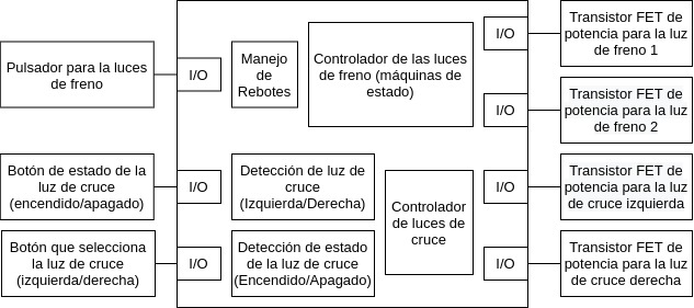
Figure 11: software block diagram.
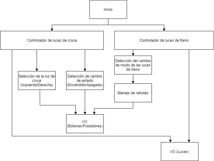
Figure 12: software hierarchy diagram.
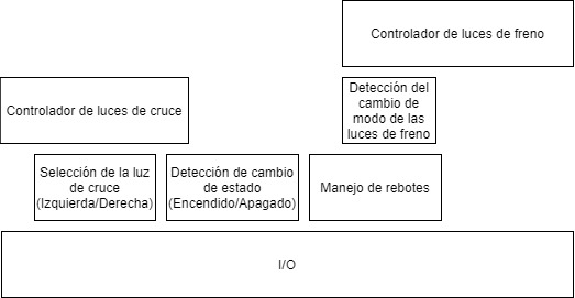
Figure 13: software layer diagram.
PCB and Enclosure
As an extra step, the PCB for the complete system was designed in Altium Designer; the results are shown below.
Figure 14: system PCB, view 1.
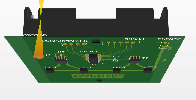
Figure 15: system PCB, view 2.
Finally, to complete a mechanical design prototype, an enclosure was modelled in AutoCAD. The final results are shown below.
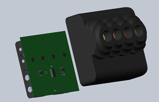
Figure 16: PCB enclosure.
The final sale prices fall within the required range and, depending on the configuration and order size, this solution offers more value at a competitive price.