Brushless DC Motor Drivers
A digital control interface for the Kelly KEB72601XF brushless‑DC motor controllers used by the USB Solar team (the Universidad Simón Bolívar solar car). The Kelly controllers give you the power hardware but expect mechanical switches and potentiometers on their input connector; this project replaces those with an Arduino Uno driven over serial, so a control board can set the motor's speed and direction.
Step 1Define
Why
Built for the course EC‑4162 — Diseño y construcción de un carro solar II (Universidad Simón Bolívar, Sep–Dec 2016).
The motor drivers Kelly KEB72601XF (24–72 V, 6 kW) provide the necessary hardware to drive brushless DC motors, but their interface is not fully digital: the wiring in the user manual uses two potentiometers for the 0–5 V throttle and brake inputs and three switches for the micro, reverse and brake signals. In this project a circuit is designed to drive that interface digitally from a development board and change the speed and direction of the motors.
Kelly Controller Specifications.
Kelly Controller Connections help.
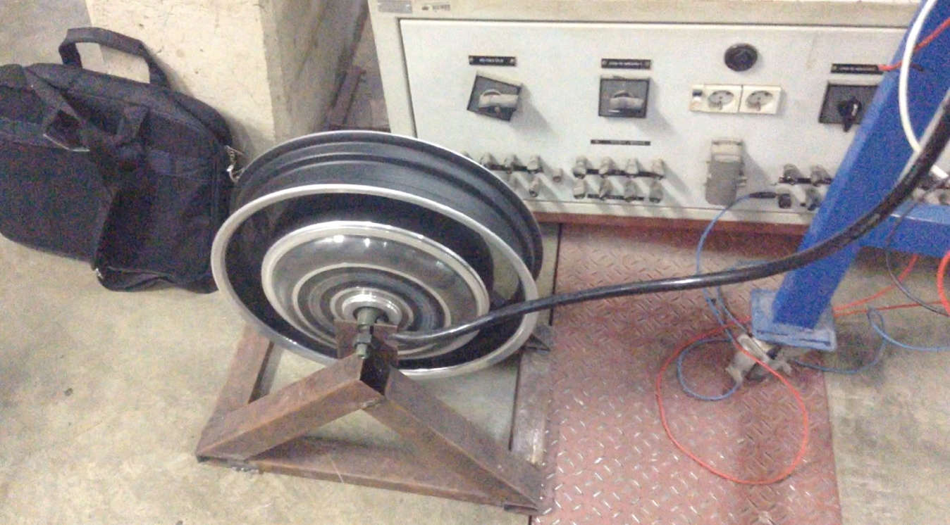
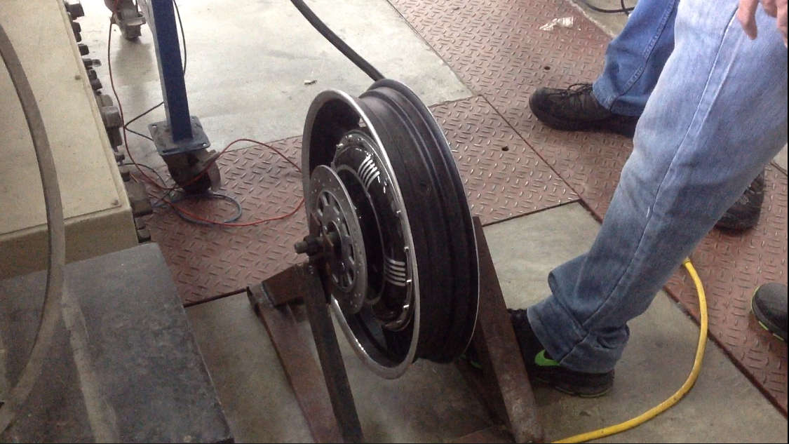
Brushless DC Motor.
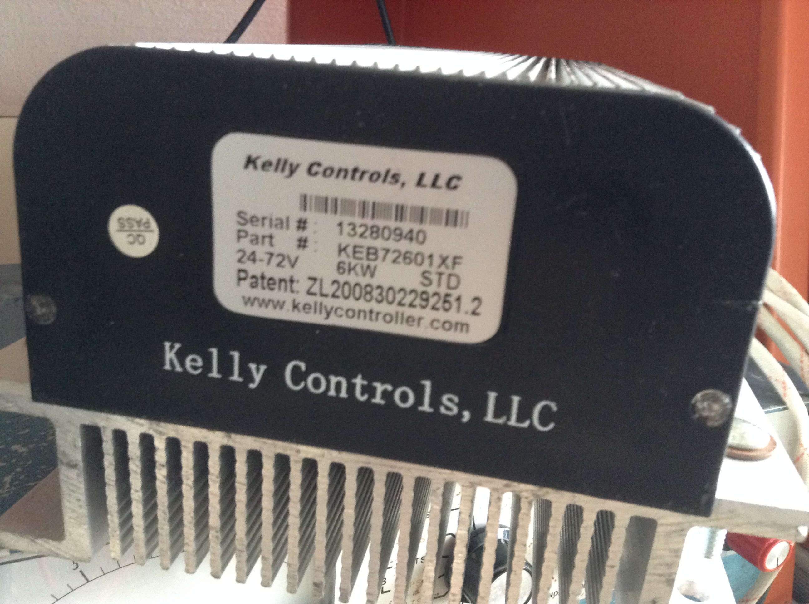
Motor driver Kelly KEB72601XF.
What It Had to Do
The 2016 course report sets two objectives: build a test rig for the controllers, and check that both of them could accelerate, decelerate and change the direction of the motors. The rest follows from where the controllers were going — onto the new solar car, driven by a control board instead of by hand:
- ControlSet each motor's speed and direction from a development board, not from knobs and switches
- MotionForward and reverse, at different speeds
- InterfaceDrive the controller's own
J2inputs: two 0–5 V analog lines and three switch lines - HostTake commands over a serial link: a PC on the bench, the car's control board later
- VerifyCheck both controllers, one new and one used, before they go on the car
Step 3Build
Circuit
The manual of the controller recommends the circuit presented in the following figure to create an interface with it. In the next figure two potentiometers and three switches are used to accelerate (throttle), decelerate (brake) and change the direction of the motor.
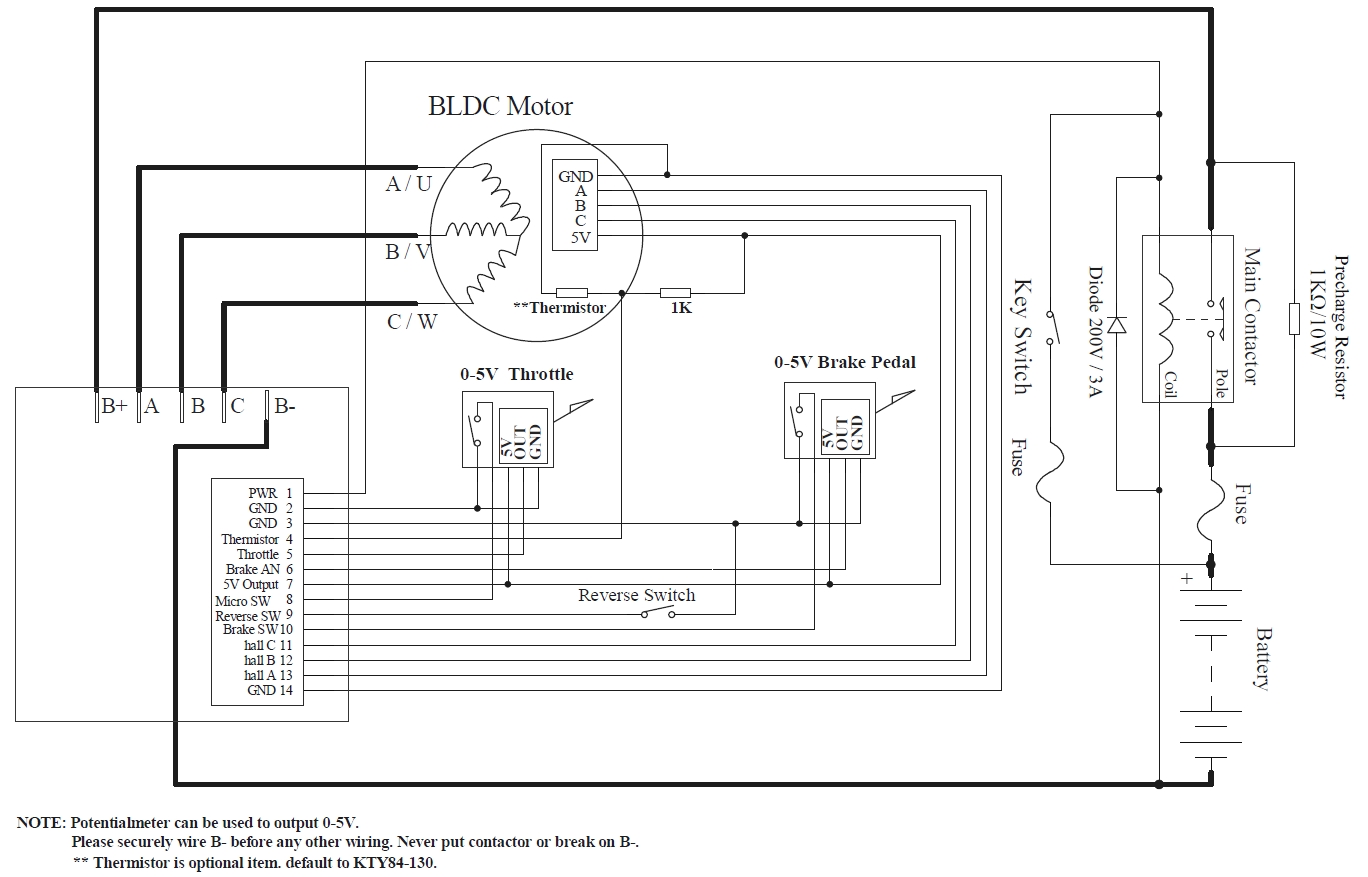
Recommended interface for the Kelly KEB72601XF From the Kelly KEB controller manual.
Three electrical relays replace the switches from the original circuit — each pulls a J2 input to ground:
- the micro / main switch that enables the accelerator;
- the brake switch that engages the decelerator;
- the reverse switch that changes the direction of rotation.
Each relay coil is switched by a transistor (with a base resistor), because the coil draws more current than an Arduino pin can source.
For the throttle and brake analog inputs (0–5 V on J2 pins 5 and 6), the Arduino emits a PWM signal that is smoothed to an analog level. A spare potentiometer is kept on the breadboard as a fallback in case a PWM channel misbehaves.
The power supply is connected to the front panel of the controller. The next image presents a description of the front panel.
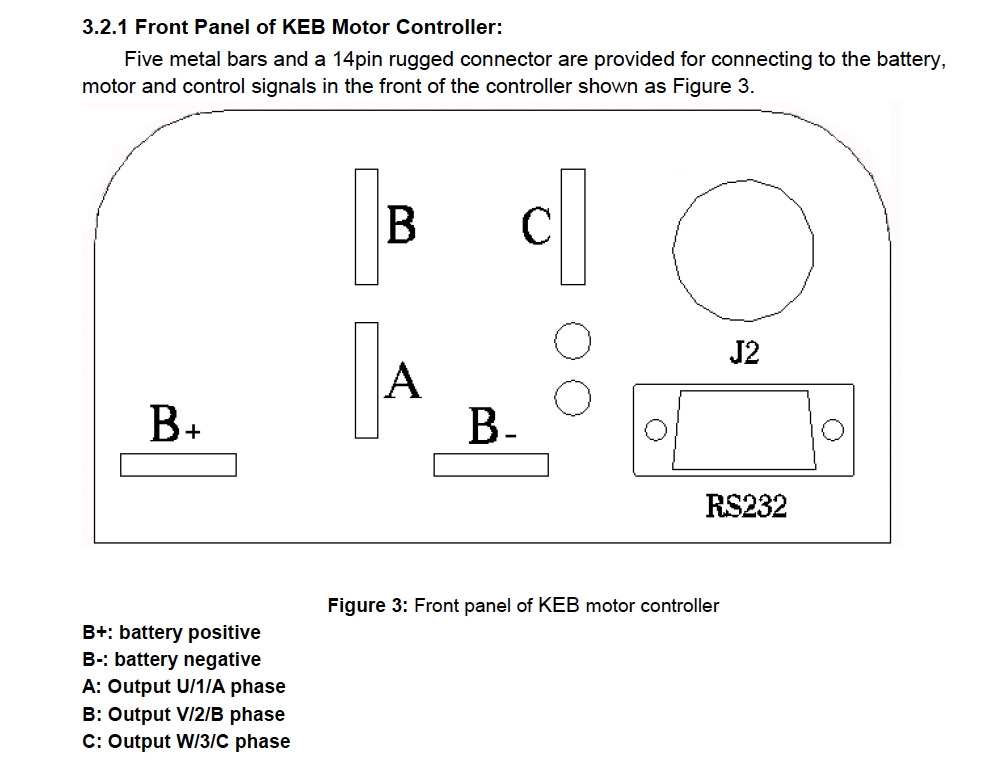
Front Panel of the Kelly KEB72601XF From the Kelly KEB controller manual.
The J2 connector is used to interact with the controller using a development board (Arduino Uno), the next image describes the J2 connector.
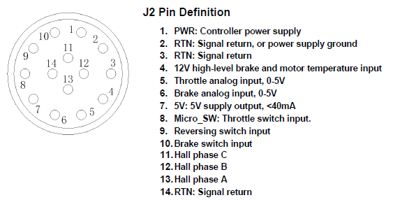
J2 Pin Description From the Kelly KEB controller manual.
Firmware
The Arduino sketch is a small serial‑to‑I/O bridge. It drives two motors — M1 (right) and M2 (left) — so the same board can run a dual‑motor rear axle:
| Function | Motor 1 (right) | Motor 2 (left) |
|---|---|---|
| Forward relay | D4 | D8 |
| Reverse relay | D5 | D9 |
| Brake relay | D7 | D10 |
| Throttle (PWM → analog) | D6 | D11 |
The relays are active‑low — every pin is driven HIGH at start‑up so all relays are released. The host talks to the Arduino at 9600 baud; each line begins with a one‑character tag:
| Line | Effect |
|---|---|
$F | both throttles to 0, then motor 1 forward relay on / reverse off |
$R | both throttles to 0, then motor 1 reverse relay on / forward off |
R<0–255> | set motor 1 throttle (analogWrite on D6) |
L<0–255> | set motor 2 throttle (analogWrite on D11) |
Everything received is echoed back for debugging. Per‑motor direction and brake commands (1FON, 2ROFF, …) are in the source but left commented out.
On the Car — the CompactRIO
On the bench the host on the serial port is a PC. On the car it is a NI CompactRIO (a real‑time controller with an FPGA) running LabVIEW: it reads the driver's pedals and commands and sends the same tagged serial lines to the Arduino, which drives the two Kelly controllers.
Step 4Test
Testing
The next images show the designed circuit (on a breadboard). Including a computer that controls the Arduino UNO using serial communication.
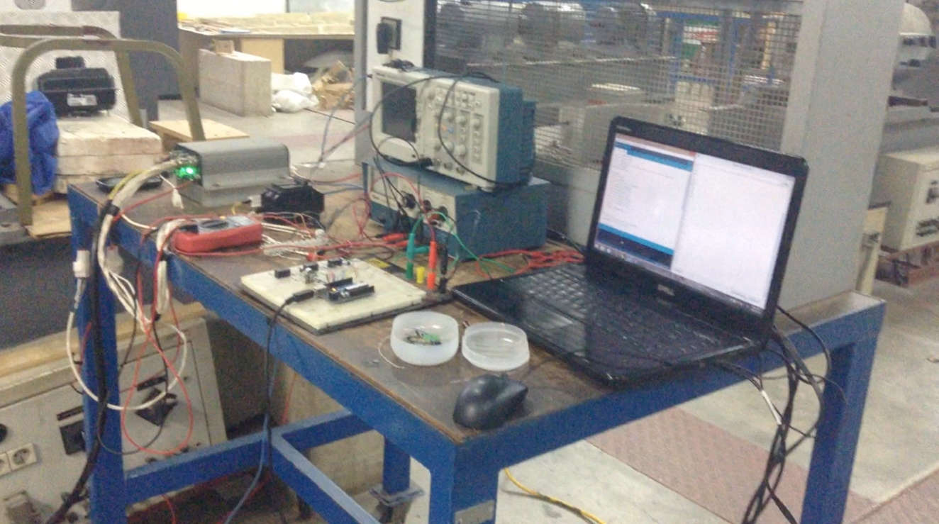
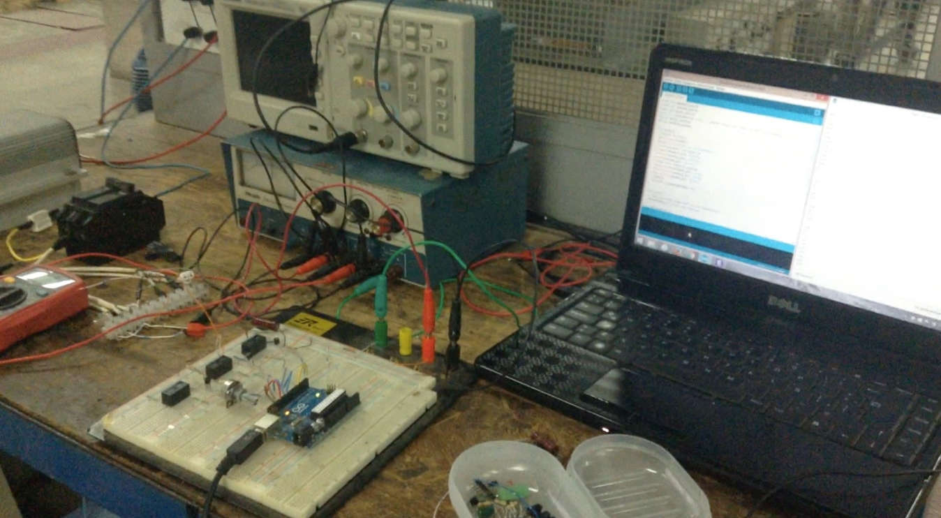
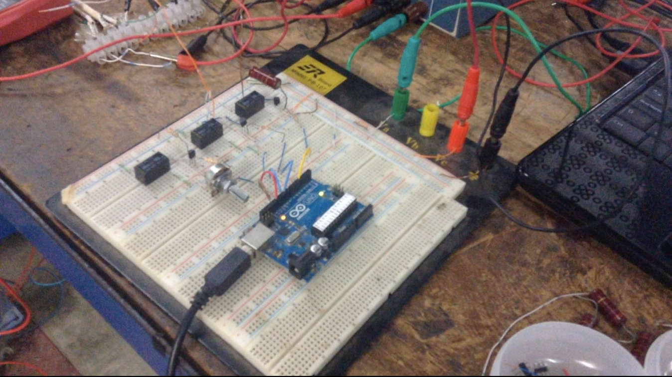
Circuit Implementation.
Results
Two Kelly KEB72601XF controllers were bench‑tested against one motor before being fitted to the car — one new and one previously used:
- The new controller worked correctly — accelerate, decelerate and reverse, all driven through the Arduino and the relay switches.
- The used controller could accelerate and decelerate in one direction but failed on direction change. It was opened up; the fault was not a quick fix, so testing stopped and it was recommended for replacement.
Step 5Refine
Recommended Changes
My report's other recommendation: replace the relay‑based switches with transistor‑based ones. The board already carries the three transistors that energise the relay coils, so the relays could be dropped entirely — simpler, and lower current draw.
Posted In:
Robotics