GPS Development Board | ANTENOVA M20050-1 and ATGM332D-5N31
This project contains the design of a development board for the ANTENOVA M20050-1 and the ATGM332D-5N31. The PCB was designed using KiCad.
Schematic
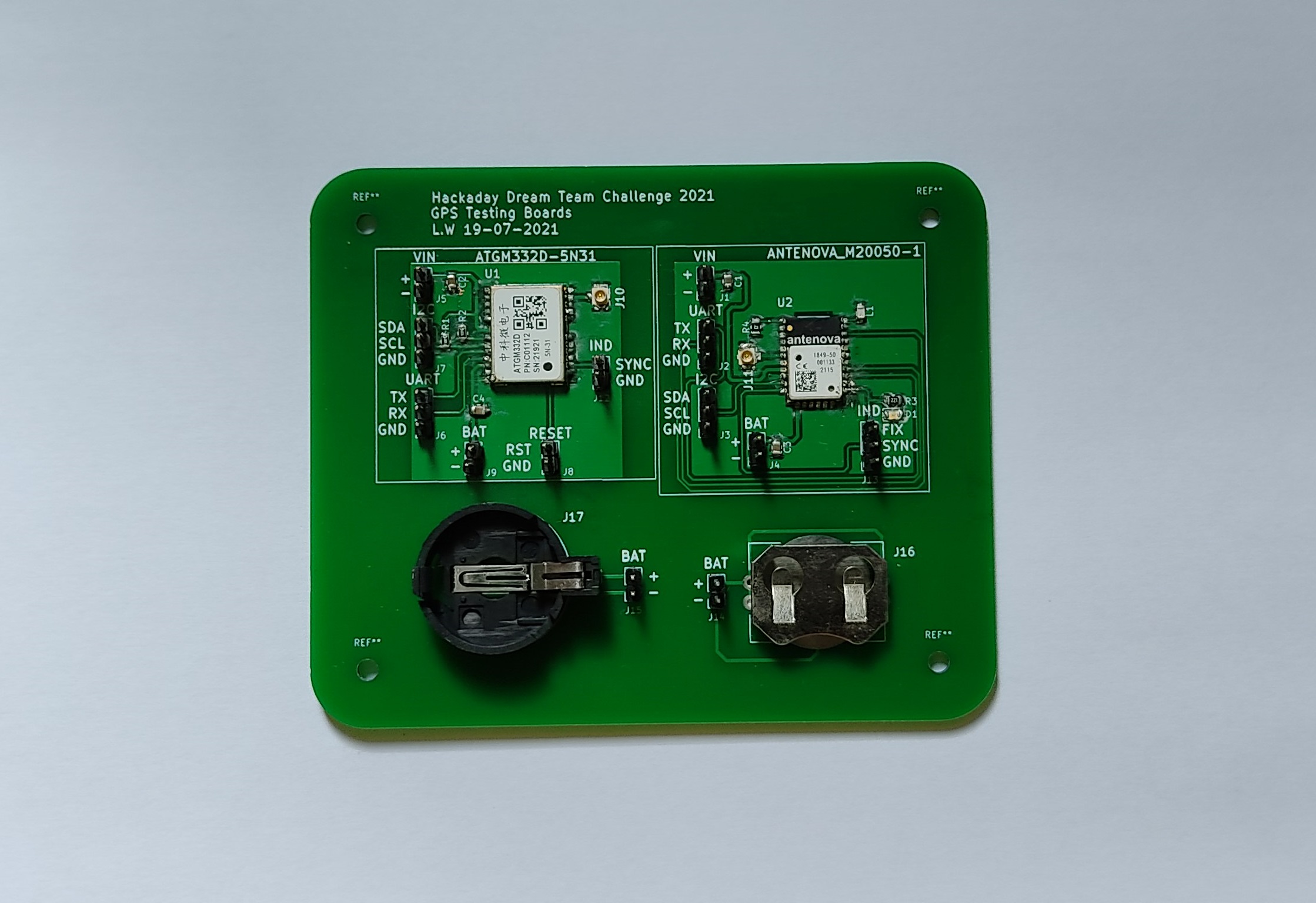
ANTENOVA M20050-1
Schematic of the GPS Dev Board: Circuit for the GPS ANTENOVA M20050-1.
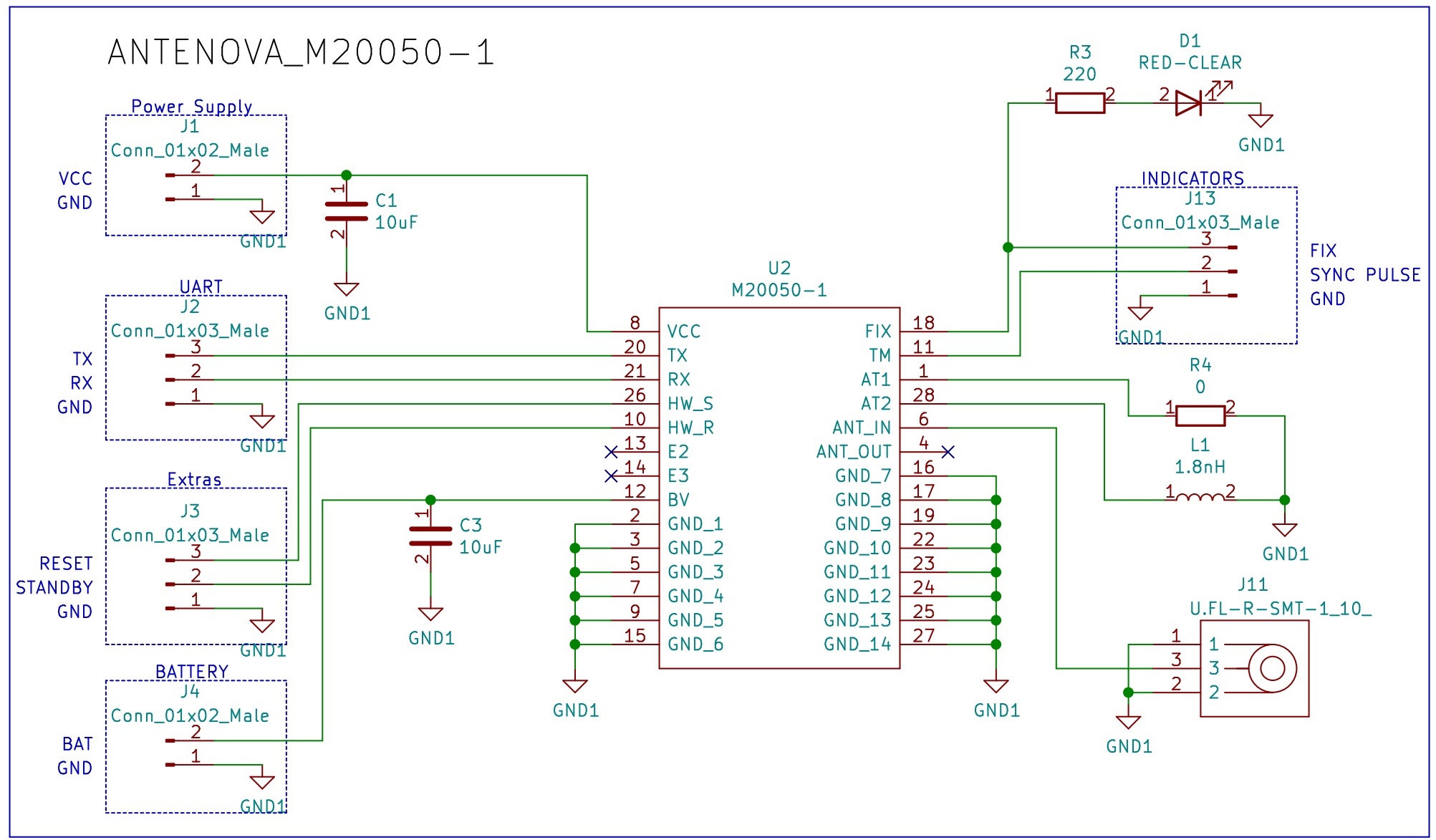
ATGM332D-5N31
Schematic of the GPS Dev Board: Circuit for the GPS ATGM332D-5N31.
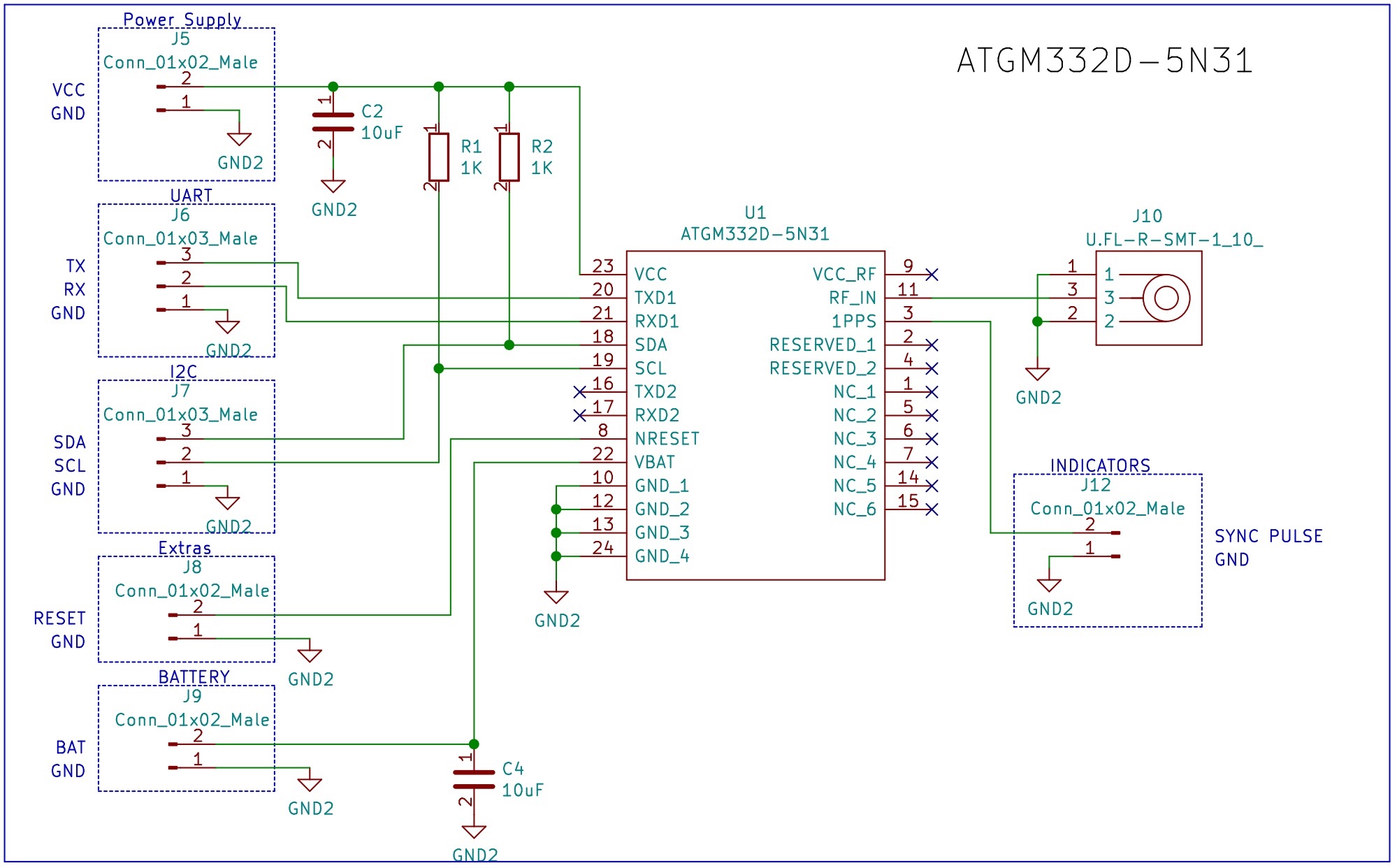
Additional Coin Battery Holders
Schematic of the GPS Dev Board: Circuit to test coin cell battery holders.
Bill of Materials
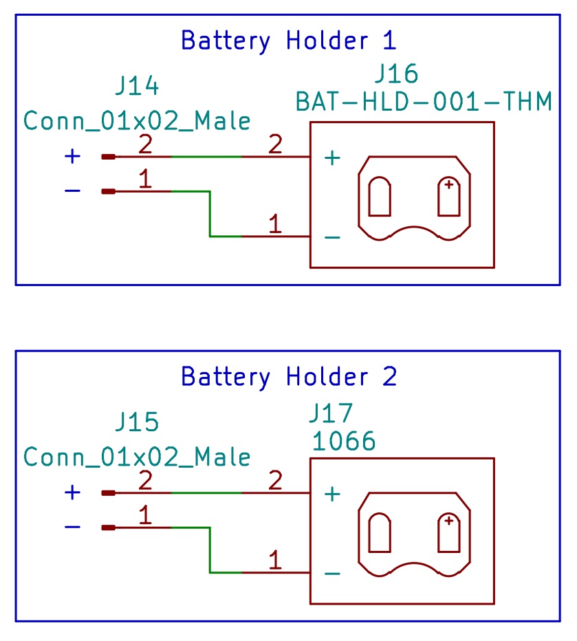
PCB
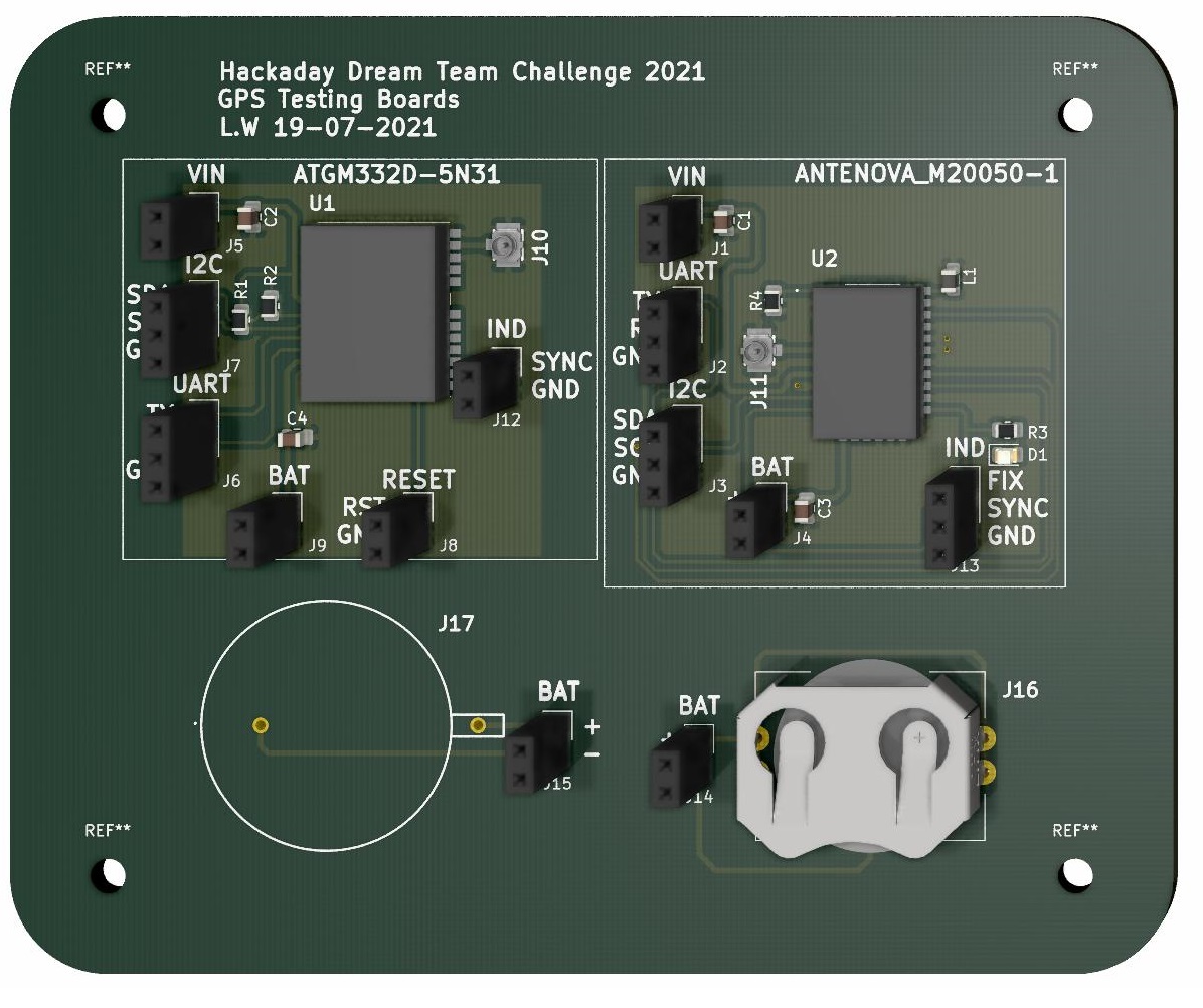
3D Model of the PCB design of the GPS Dev Board.
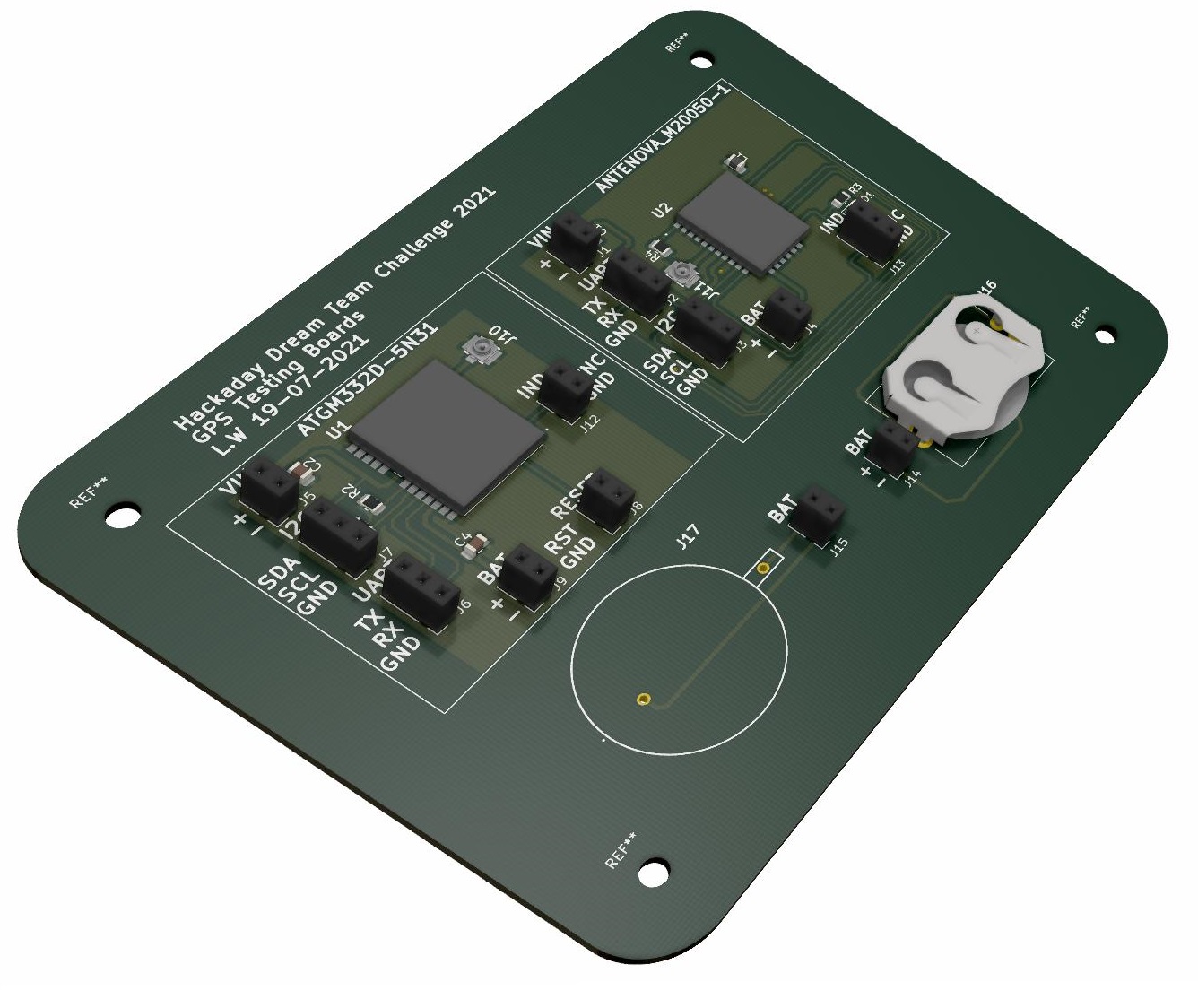
3D Model of the PCB design of the GPS Dev Board.
Posted In:
Embedded Hardware