FTDI Development Board | FT260S and FT312D
This project contains the design of a development board for the FT260S and the FT312D. The PCB was designed using KiCad.
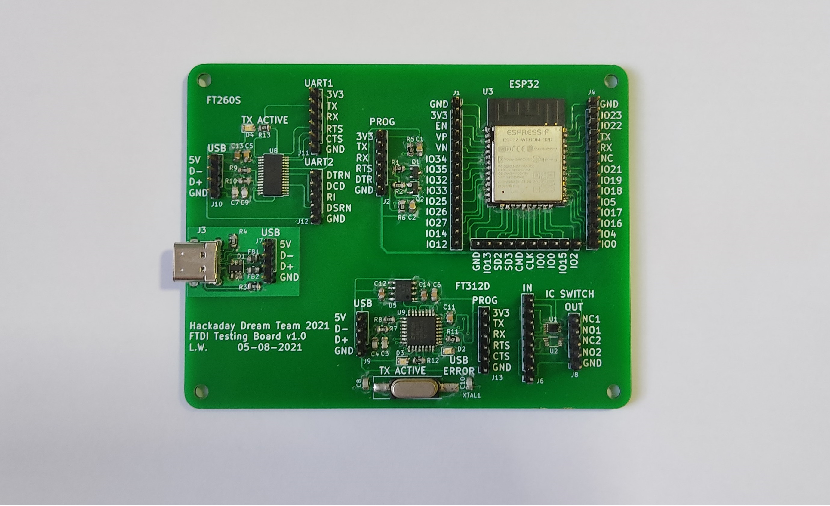
Hardware Design
USB C Port with Electromagnetic Compatibility EMC
Everything starts with the USB C port, this type of USB was selected because it's size and because of the growing trend of using this port to charge and communicate with portable devices.
The design includes Transient Voltage Suppression (TVS) diodes and Ferrite Beads to reduce the Electromagnetic Interference (EMI). These protections for the USB port will add compliance with the EMC regulations and standards from the Federal Communications Commission (FCC) and the European Union.
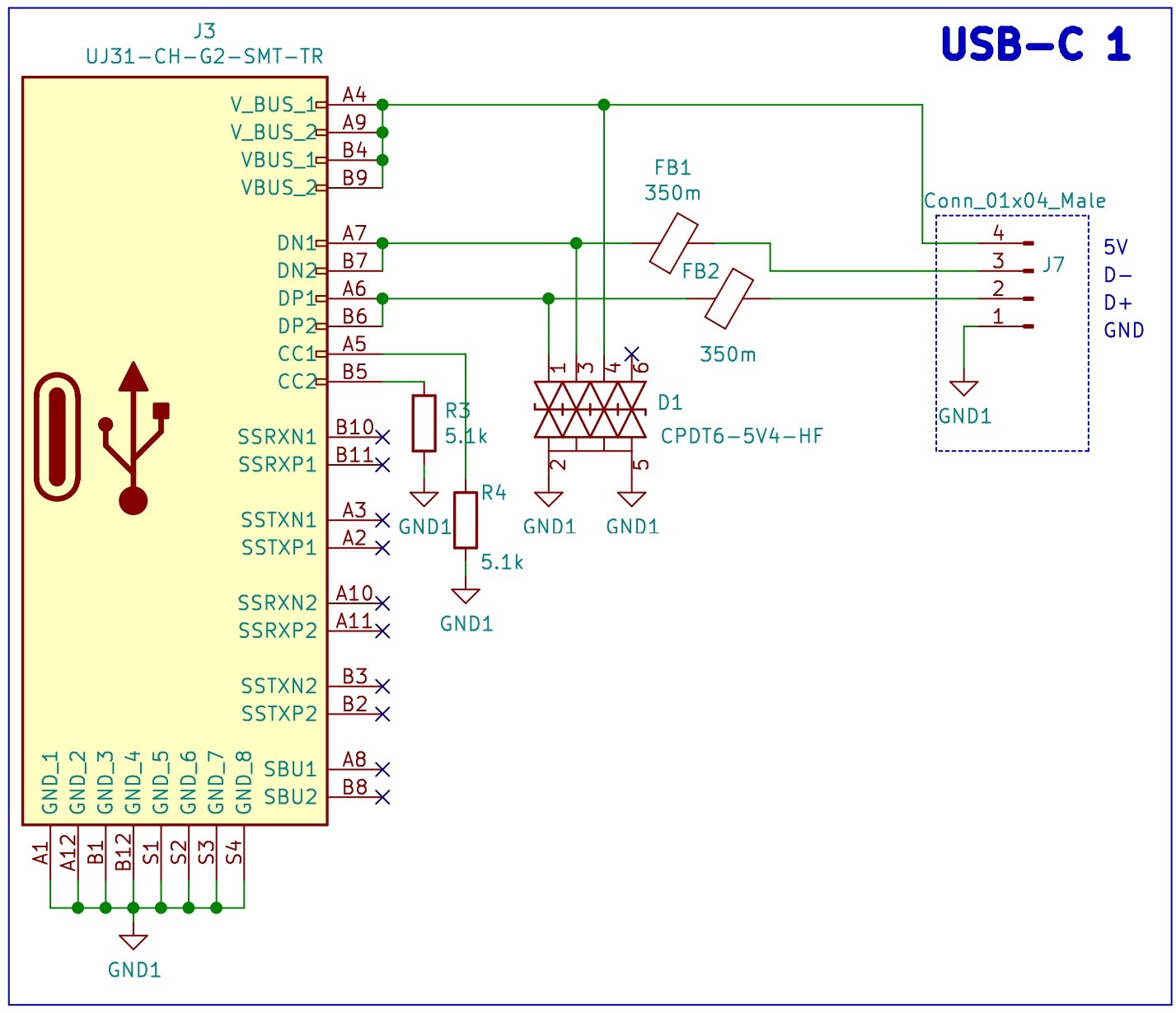
Schematic of the FTDI Dev Board: USB C and EMC protections.
FTDI 1 - FT260S
The first USB TO UART/I2C FTDI that we is being tested is the FT260S-U. The design only considers the USB to UART, therefore the I2C is left unconnected.
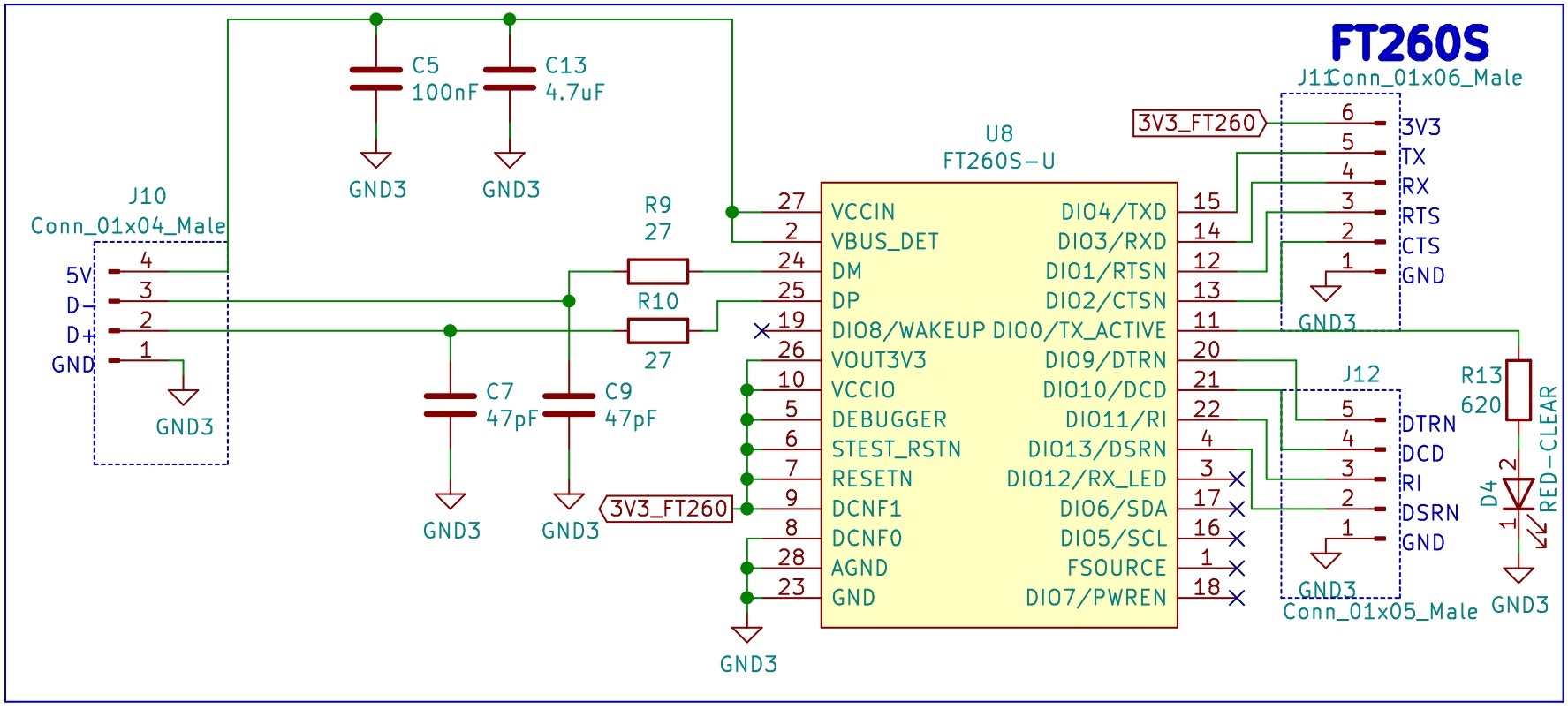
Schematic of the FTDI Dev Board: Circuit for the FTDI FT260S-U.
Notes: The FT260S was originally selected to directly program the ESP32, and also provide serial communication. After careful consideration I found that the FT260 is a HID class device and as such it does not generate a Virtual COM Port (like the FT232R), to interface with the FT260 it can be used the official helper library, LibFT260.
https://www.ftdichip.com/Support/Documents/AppNotes/AN_394_User_Guide_for_FT260.pdf
https://www.ftdichip.com/Support/Documents/AppNotes/AN_395_User_Guide_for_LibFT260.pdf
For that reason the FT260S will require more work before it can seamlessly program the ESP32. This topic will have to be addressed in the future.
FTDI 2 - FT312D
The second USB TO UART/I2C FTDI that is being tested is the FT312D-32L1C-R. This IC does not support DTR/DSR for the UART, a feature that is required for the auto reset circuit of the ESP32 that was implemented, nevertheless the PCB has it as a second alternative.
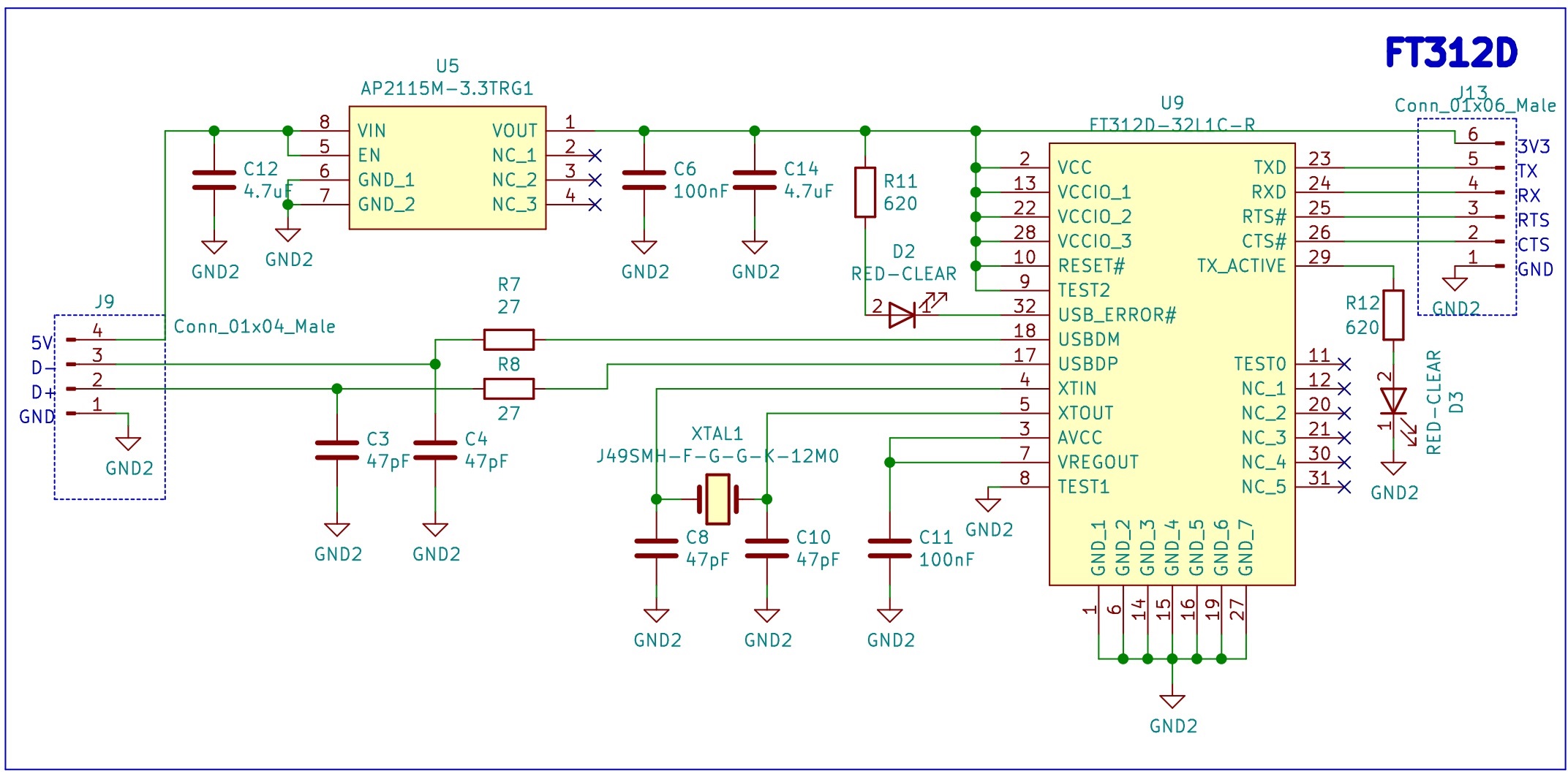
Schematic of the FTDI Dev Board: Circuit for the FTDI FT312D-32L1C-R.
ESP32 with Auto Reset
Finally, the ESP32. The design includes an auto reset circuit that uses RTS and DTR to reset and put in bootloader mode the ESP32. For more information about this circuit, these blogs [1] [2] can be useful.
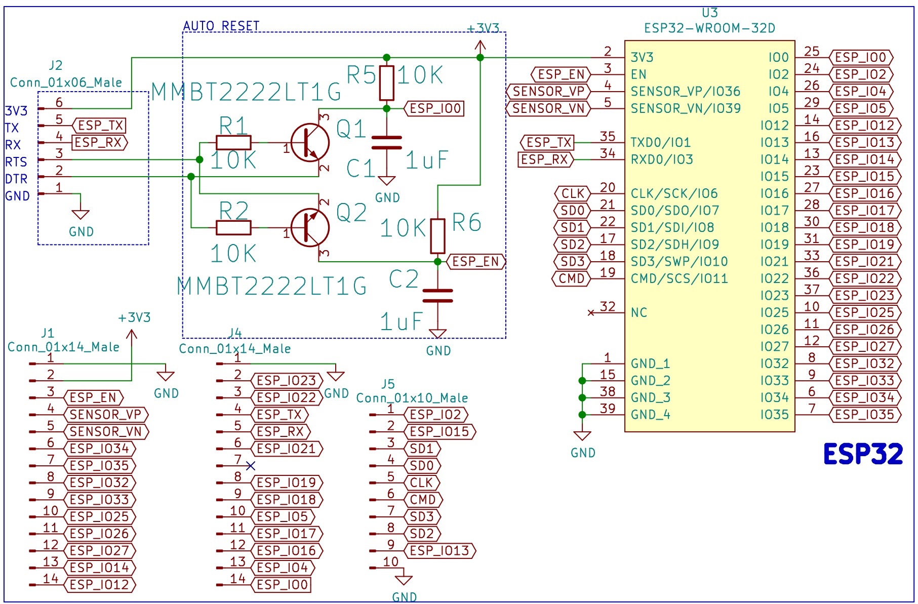
Schematic of the FTDI Dev Board: Auto reset circuit for the ESP32.
SPDT Switch
The design includes a couple of TS5A3153DCUR that will be tested for future implementations.
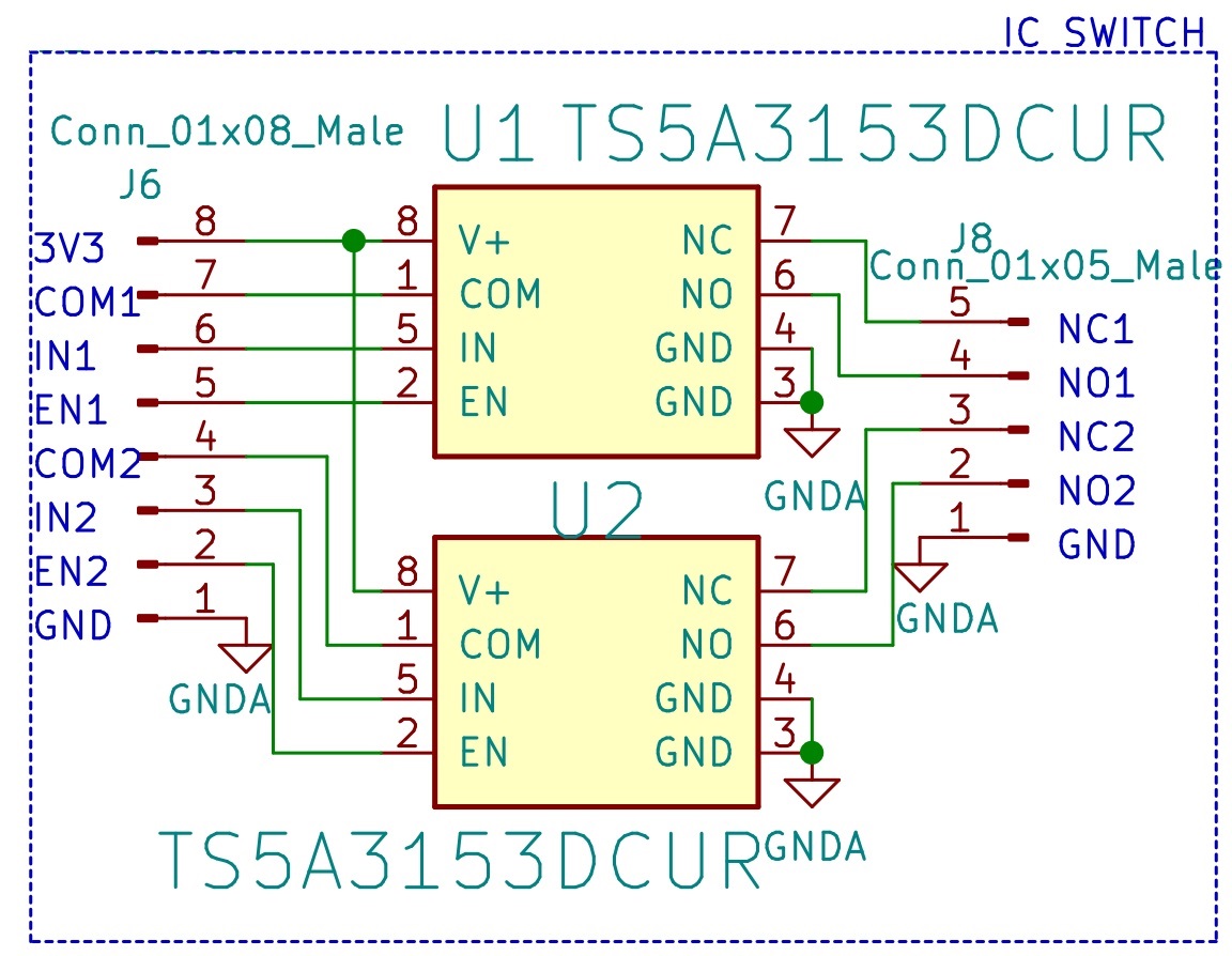
Schematic of the FTDI Dev Board: Circuit for the SPDT switch TS5A3153DCUR.
Bill of Materials
PCB
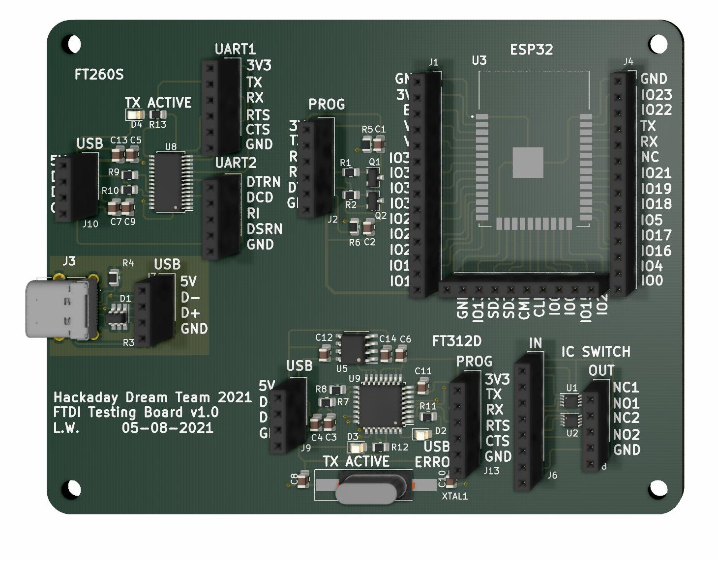
3D Model of the PCB design of the FTDI Dev Board.
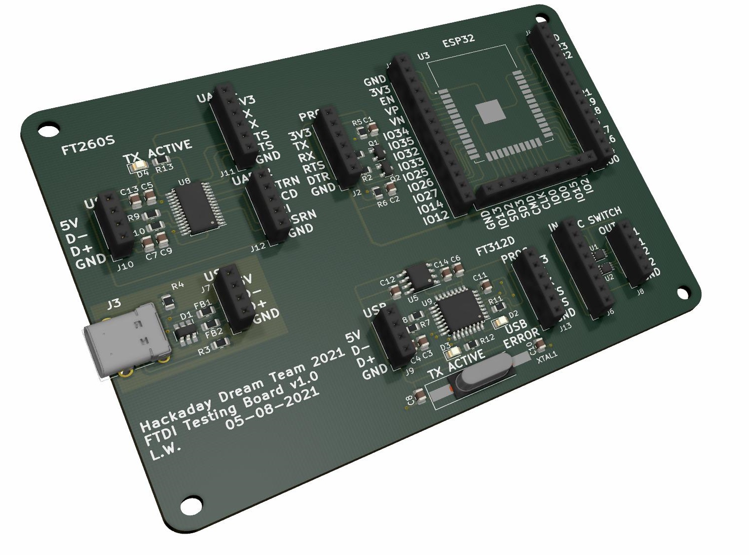
3D Model of the PCB design of the FTDI Dev Board.
Testing
The designed auto reset circuit requires the signals 3.3V, GND, TX, RX, RTS and DTR. The commercial USB to Serial Converter (FT232RL) was used to test the circuit, it provides all the required signals.
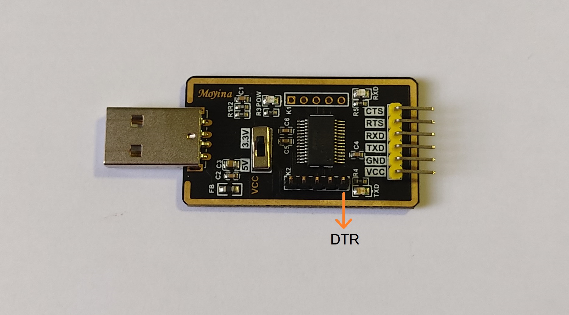
Commercial USB to Serial Converter used for testing.
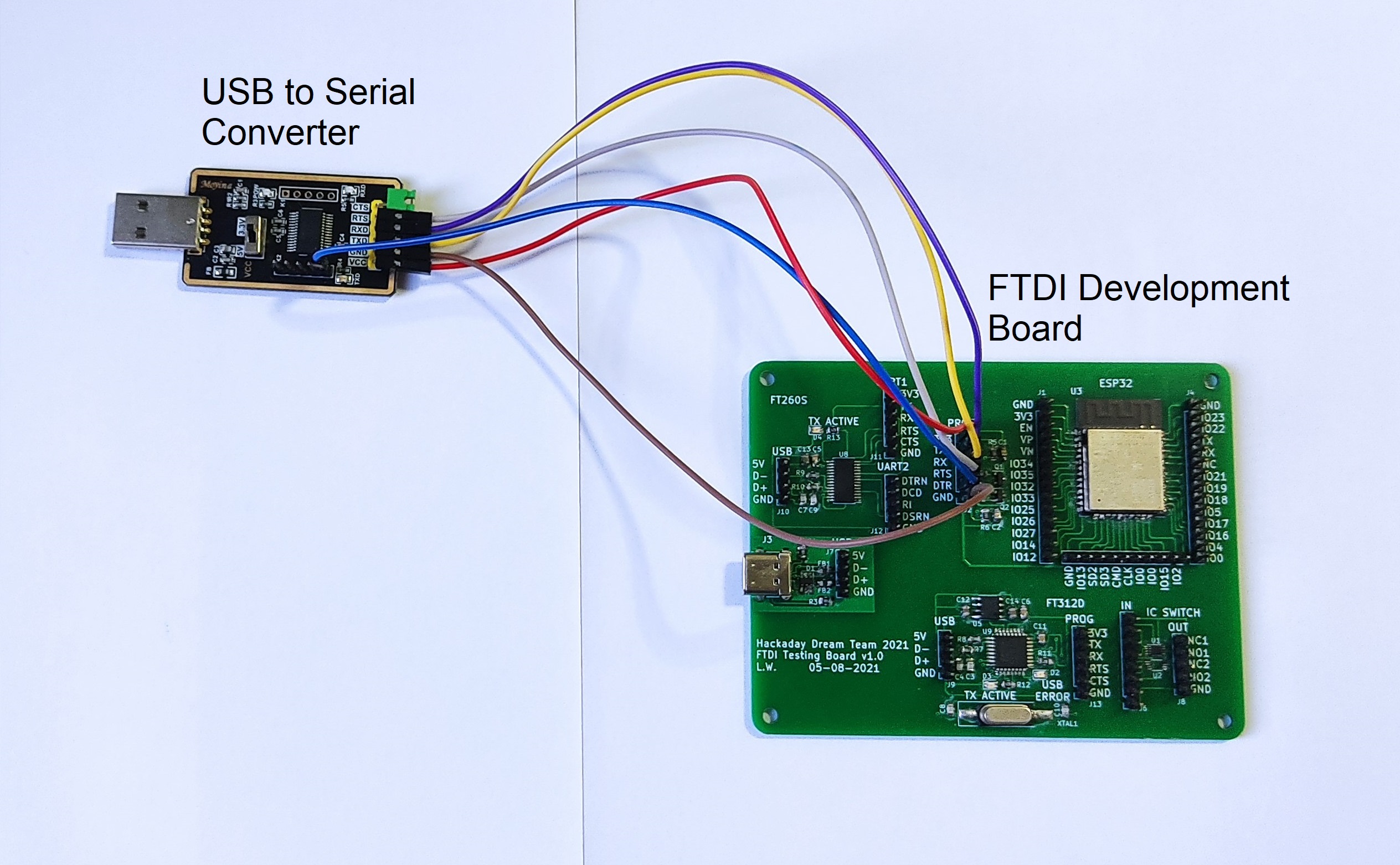
The following wiring diagram shows how to connect the commercial USB to Serial Converter and our FTDI Development Board.
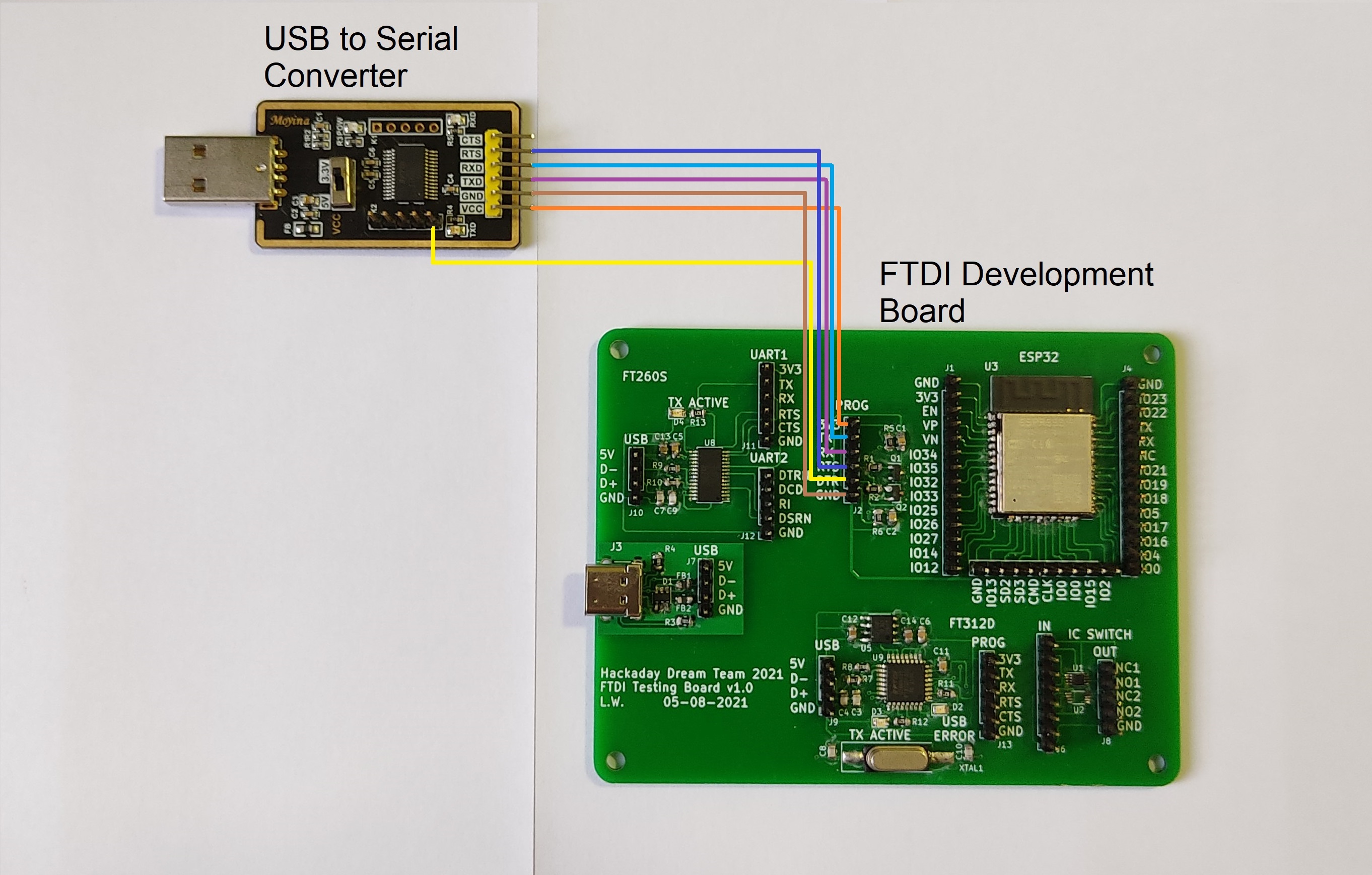
Wiring diagram for the FTDI Dev Board and the Commercial USB to Serial Converter.
Wiring diagram for the FTDI Dev Board and the Commercial USB to Serial Converter.
Once the 2 boards were connected and the USB to Serial Converter was plugged, the PC (in Windows) recognized the device and it was ready to use. Check if you need to install drivers associated to the FTDI, that is often the case.
Note: Before testing the following code, verify that the ESP-IDF is installed and the Arduino IDE can program ESP devices.
The code used is very simple, the ESP32 sends a "Hello world" message through the serial communication every second.
                  void setup() {
                     Serial.begin(115200);
                  }

                  void loop() {
                     Serial.println("Hello World");
                     delay(1000);
                  }
The standard Arduino IDE was used to program the ESP32, with the following configurations:
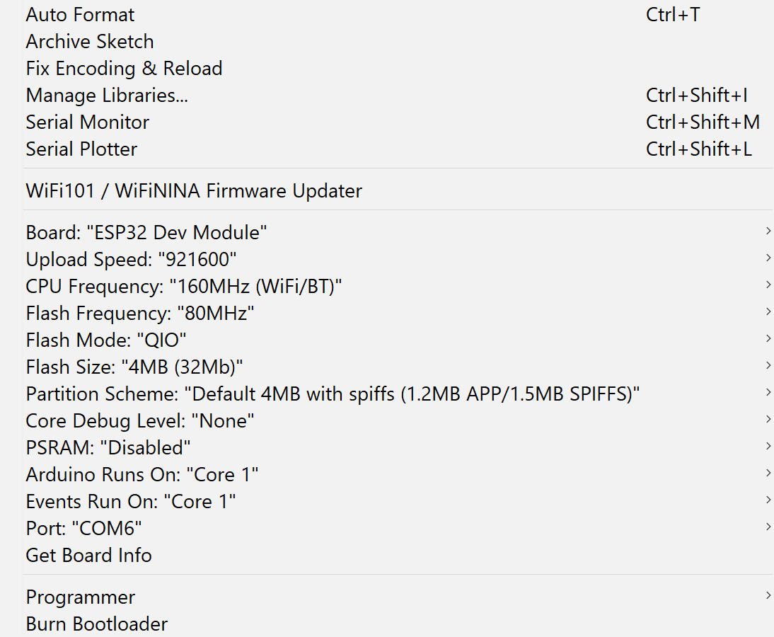
Setup of the Arduino IDE for the test.
And the test was successful, the following image shows the results in the serial monitor.
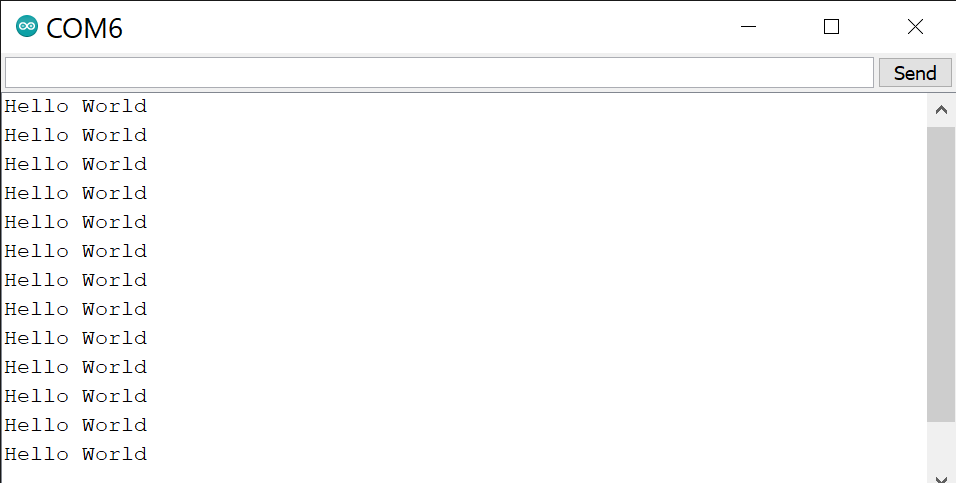
Results of the test.
Posted In:
Embedded Hardware