Brake Test Data Logger
An axle‑tip acceleration logger for Baja SAE USB brake tests (Universidad Simón Bolívar, División de Electrónica). A hand‑formed metal box bolts straight onto a wheel hub and logs 3‑axis acceleration to an SD card as the car is driven and braked — closer to the wheel/road interface than a chassis‑mounted sensor, and self‑contained rather than needing a live telemetry link. Another of the Baja SAE USB electronics sub‑systems — December 2013.
Step 1Define
Why
Our team's existing telemetry system — a prior thesis project built around Freescale MCUs, GPS, a gyroscope, Hall‑effect and IR sensors, and XBee/ZigBee links into a CAN network, all displayed live in LabVIEW — is a full vehicle telemetry suite. For a focused brake test, that's a lot of system to bring up. This logger is the opposite trade‑off: one sensor, one axis of the car, no radio link, no live display — just an accelerometer at the axle tip and a microSD card, small enough to bolt onto a wheel and forget about until the run is over.
What It Had to Do
The goal was to measure the accelerations in X, Y and Z at the axle tip of our Baja prototype. The rest followed from how the logger would be used:
- MeasureX, Y and Z acceleration at the axle tip, not on the chassis
- MountBolt straight onto a wheel hub, through the wheel's own lug holes
- StandaloneNo radio link or live display: log to a microSD card and analyse after the run
- PowerRun from a single 9 V battery
- SignalKeep high‑frequency vibration from the wheel/road interface out of the log
- OrientationEvery log must map back to the car's real X, Y and Z axes
Step 2Simulate
Filter Design
Each axis is filtered twice before it reaches the ADC. The ADXL335 itself has 32 kΩ internal resistors that form an RC low‑pass with whatever capacitor sits on its X/Y/Z pins — the breakout board's 0.1 µF caps put that corner at ≈49.7 Hz. On top of that, each output runs through an external 10 kΩ + 1 µF RC low‑pass, cutting at 15.915 Hz, to knock down high‑frequency vibration from the wheel/road interface before logging.
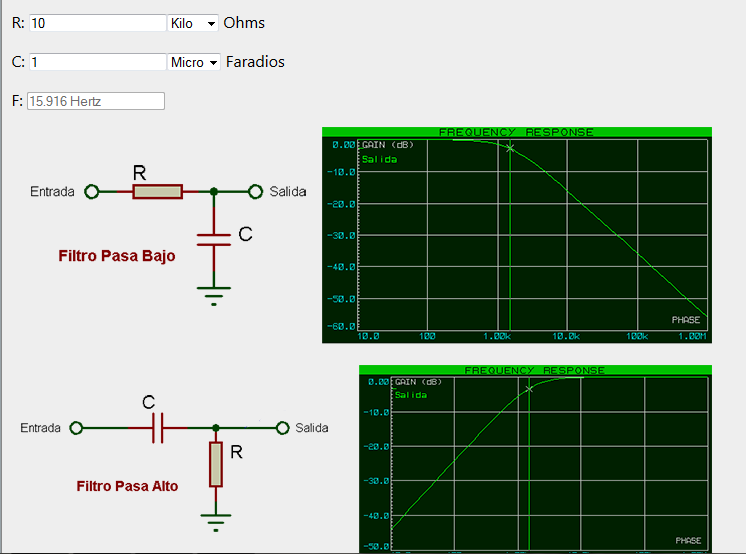
The external RC low‑pass stage and its simulated response.
Step 3Build
Hardware
An ADXL335 (±3 g, 3‑axis, analog output) on a small breakout board, wired into an Arduino Uno together with a microSD “SD Card Shield” over SPI. A single 9 V battery feeds an L7805CV (5 V, for the Arduino) and an LD33V (3.3 V, for the accelerometer), each with 4.7 nF bypass caps.
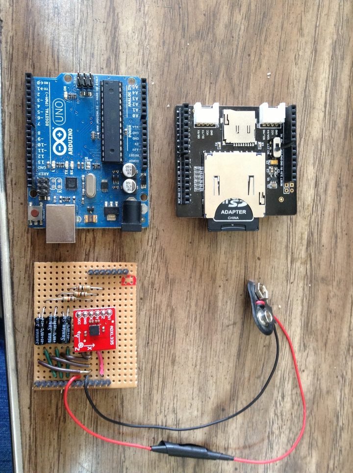
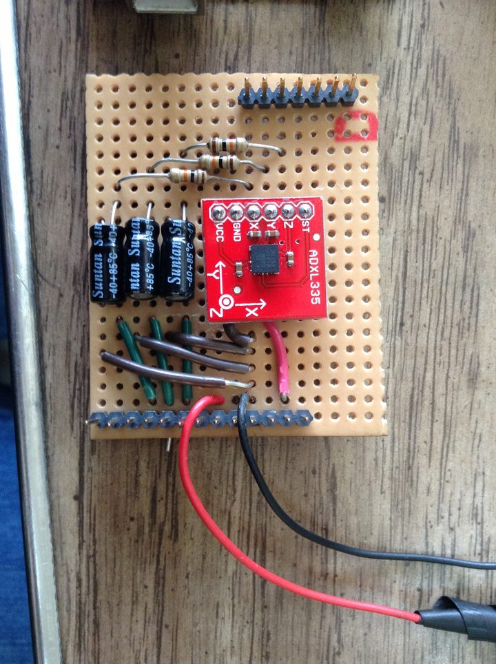
The full kit — Arduino, SD shield and battery — and a close‑up of the ADXL335 filter board.
Mounting
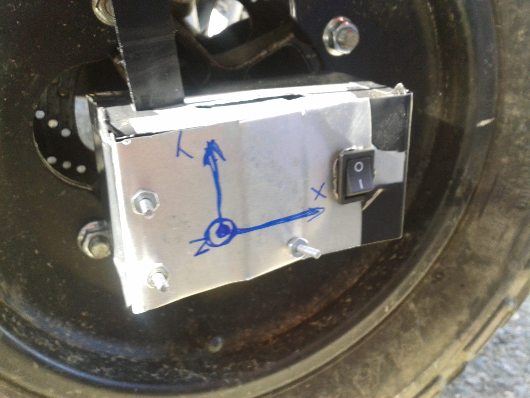
The enclosure — hand‑formed sheet metal, the sensor circuit itself on a bakelite perfboard — bolts directly to a wheel hub through the wheel's own lug holes, putting the accelerometer as close to the axle tip as the hardware allows. The X, Y and Z axes are marked in pen straight on the box so a run's raw log can be matched back to the car's real orientation during analysis; a switch on the side turns logging on and off.
Step 4Test
Calibration
The ADXL335 is a raw‑voltage sensor, so each axis still needs its own zero‑offset and scale before the logged counts mean anything. The calibration used here: with the sensor at rest, read the raw ADC count on an axis in two orientations 180° apart (+1 g and −1 g on that axis); the midpoint of the two readings is the zero‑g offset, half their difference is the 1 g scale:
acceleration [m/s²] = ( raw_count − zero_offset ) / scale × 9.80665The Data
Runs were driven and braked around Centro San Ignacio in Chacao, Caracas — a reconnaissance lap, then several braking laps per wheel (front‑right, front‑left, rear‑right), each logged as raw TIEMPO,ACEX,ACEY,ACEZ counts to the SD card and converted to m/s² afterwards with the calibration above.
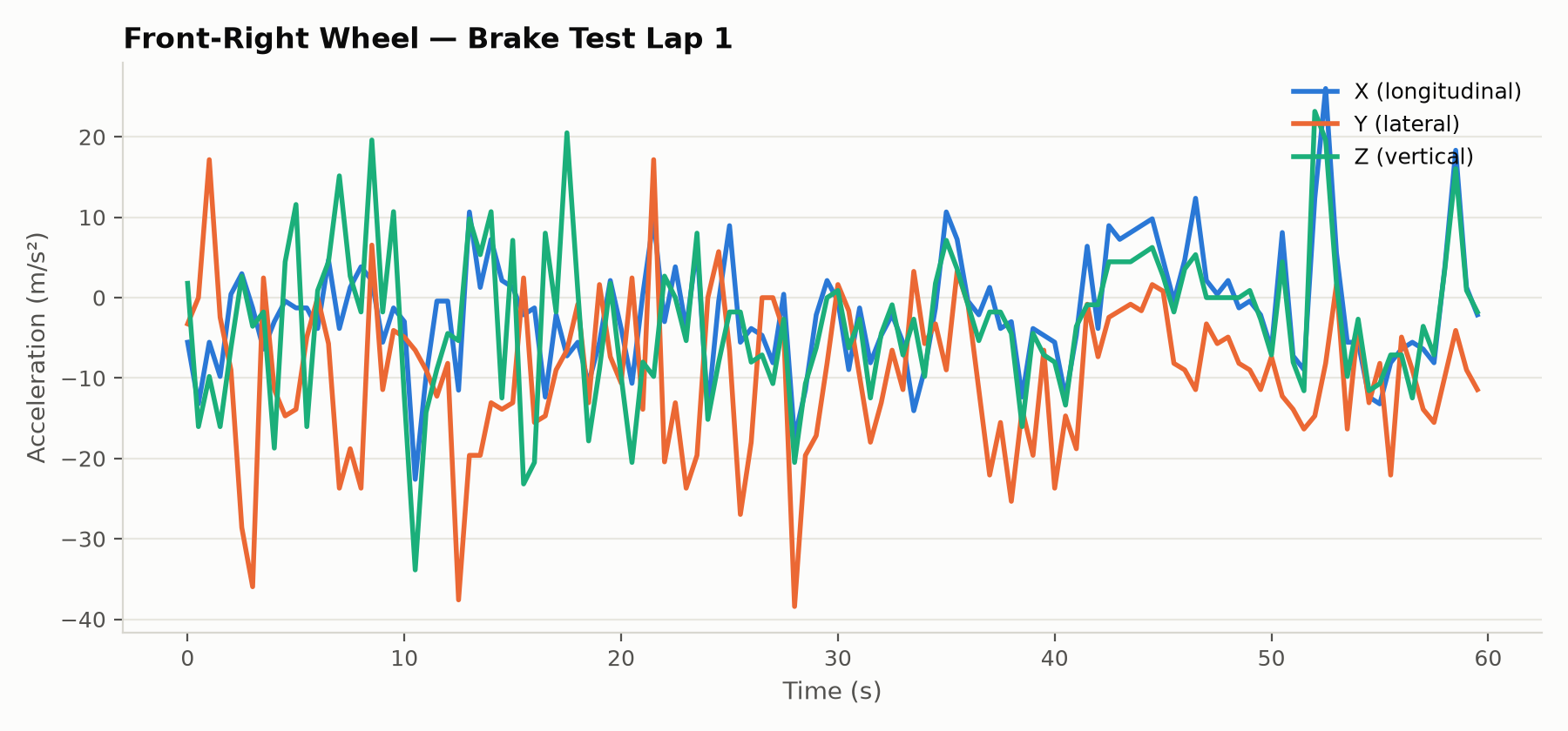
Front‑right wheel, brake‑test lap 1 — X, Y and Z acceleration over one run.
What the Data Showed
Mounted directly on the hub, the signal is dominated by wheel rotation and road texture rather than a clean braking signature — there's no obvious single deceleration spike to pick out by eye in the raw trace above; extracting a braking event from this data would need proper filtering or event detection downstream, which this project didn't get to.
Posted In:
Vehicles