Onboard Gateway | Hackaday Dream Team 2020
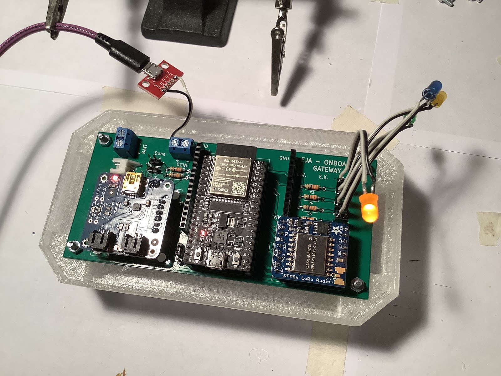
The Onboard Gateway is a 134.11 mm x 62.48 mm PCB that integrates the 3 main components (ESP32, LoRa and USB LiIon/LiPoly charger).
Main Components
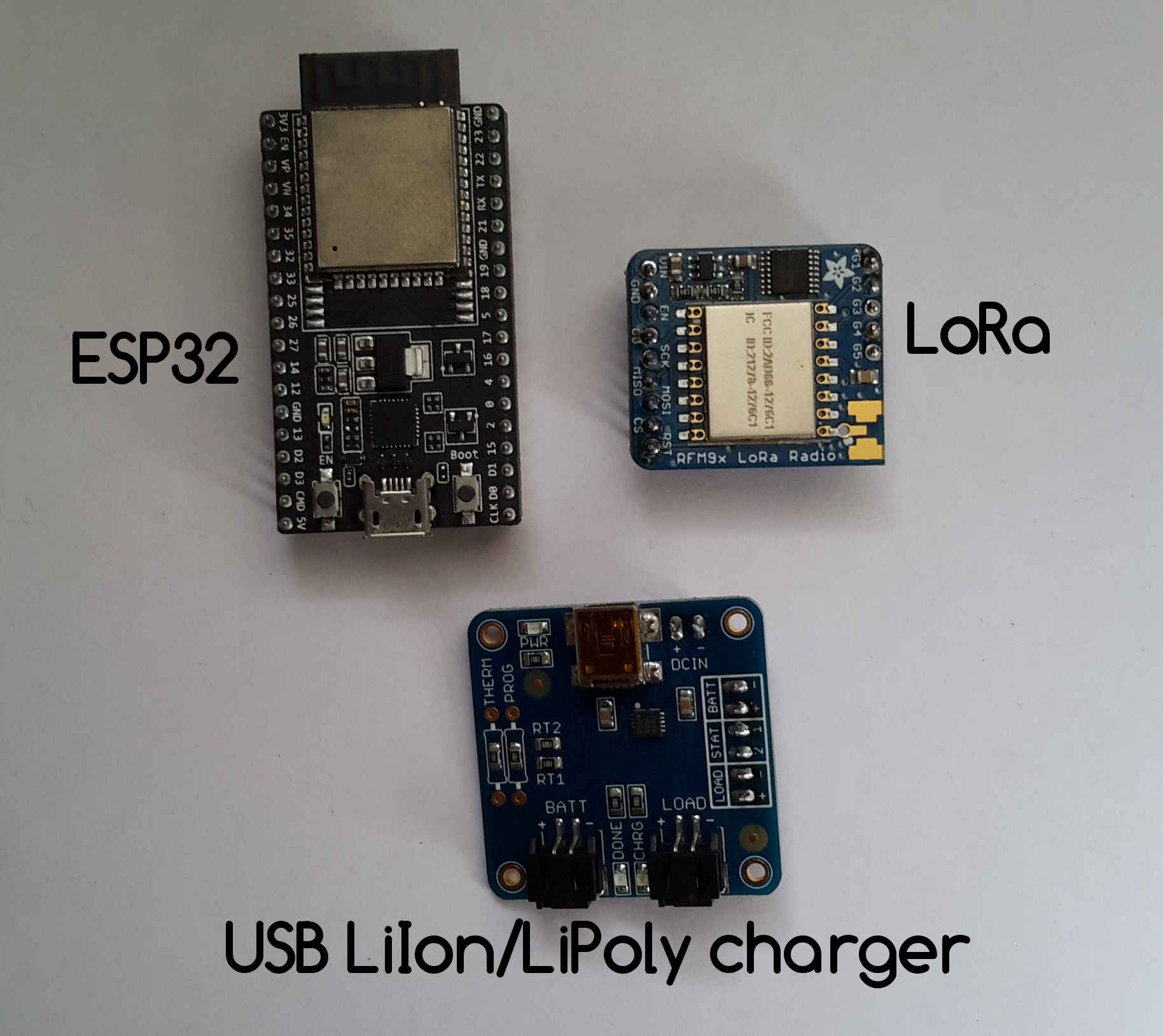
Main components of the Onboard Gateway v1.0.
Sources:
Schematic
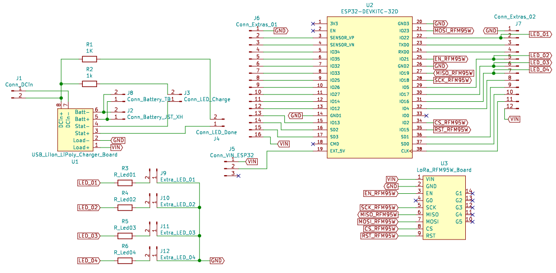
Schematic of the Onboard Gateway v1.0.
For more information about the design check the original post in the project's page.
Layout
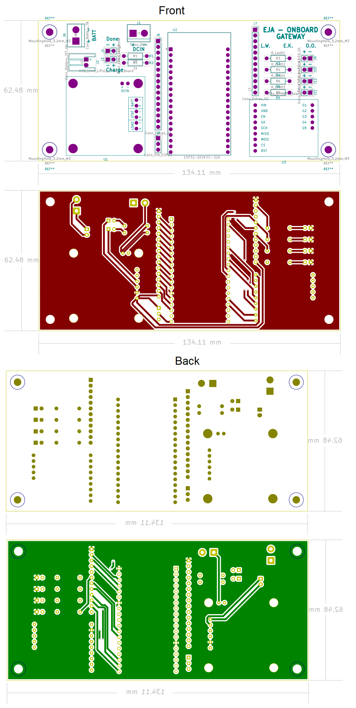
PCB Layout of the Onboard Gateway v1.0.
PCB
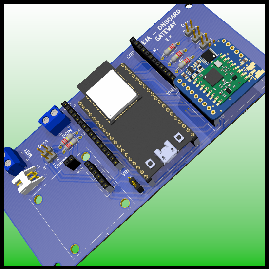
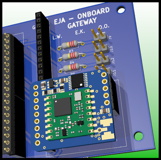
PCB Design.
PCB Design: LoRa Module.
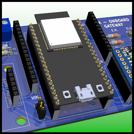
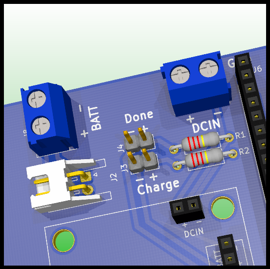
PCB Design: ESP32.
PCB Design: Battery Connection.
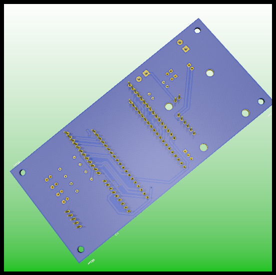
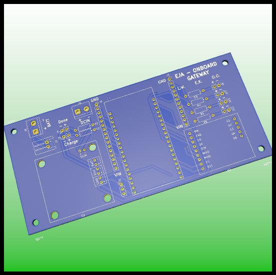
PCB Design: Front and Back.
Assembly
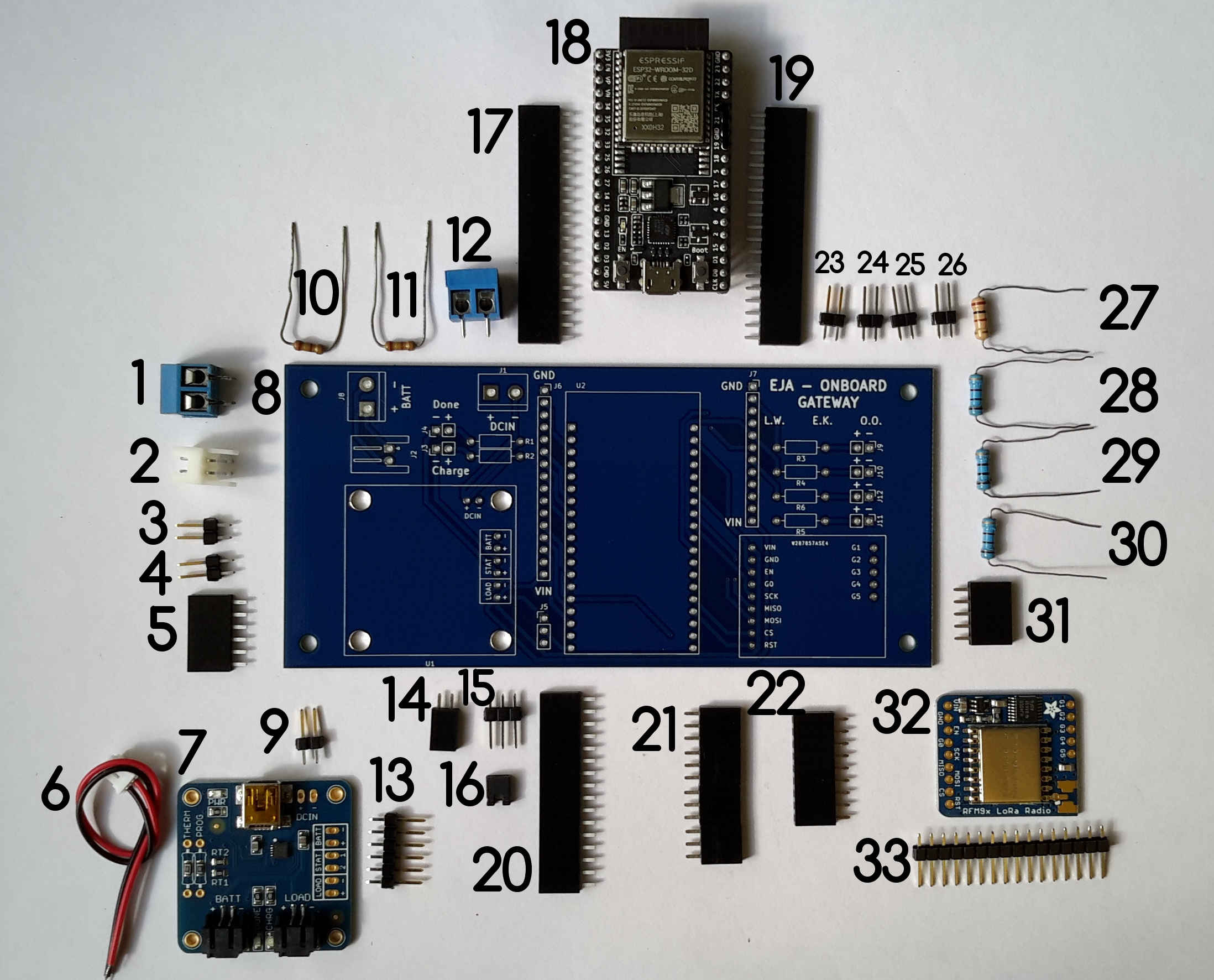
Components of the Onboard Gateway v1.0.
Components List:
- TERM BLK 2P SIDE ENT 5.08MM PCB
- CONN HEADER R/A 2POS 2.5MM
- CONN HEADER VERT 2POS 2.54MM
- CONN HEADER VERT 2POS 2.54MM
- CONN HDR 6POS 0.1 TIN PCB
- 2POS JST cable (included in the USB LiIon/LiPoly charger)
- USB LiIon/LiPoly charger
- PCB Onboard Gateway V1.0
- CONN HEADER VERT 2POS 2.54MM
- RES 249 OHM 1/4W 1% AXIAL
- RES 249 OHM 1/4W 1% AXIAL
- TERM BLK 2P SIDE ENT 5.08MM PCB
- CONN HEADER VERT 6POS 2.54MM
- CONN HDR 2POS 0.1 GOLD PCB
- CONN HEADER VERT 3POS 2.54MM
- CONN JUMPER SHORTING .100" GOLD
- CONN HDR 19POS 0.1 TIN PCB
- ESP32-DEVKITC-32D
- CONN HDR 19POS 0.1 TIN PCB
- CONN HDR 16POS 0.1 TIN PCB
- CONN HDR 12POS 0.1 TIN PCB (I used 2 CONN HDR 6POS 0.1 TIN PCB in the image)
- CONN HDR 9POS 0.1 GOLD PCB
- CONN HEADER VERT 2POS 2.54MM
- CONN HEADER VERT 2POS 2.54MM
- CONN HEADER VERT 2POS 2.54MM
- CONN HEADER VERT 2POS 2.54MM
- RES 100 OHM 3W 5% AXIAL
- RES 100 OHM 3W 5% AXIAL
- RES 100 OHM 3W 5% AXIAL
- RES 100 OHM 3W 5% AXIAL
- CONN HDR 5POS 0.1 GOLD PCB
- RFM95W LoRa Radio
- CONN HEADER VERT 16POS 2.54MM (included in RFM95W LoRa Radio)
For a detailed Bill of Materials visit the following post/a>.
For a detailed explanation about the soldering and assembly procedure visit the following post.
Wiring Diagrams
The following diagram presents the physical connections of the different boards and components of the Onboard Gateway, that includes:
- 3.7V 1 Cell Battery
- Leds (Charge, Done and 4 Miscellaneous)
- PCB Board for the Onboard Gateway V1.0
- 5V Charger (only used to charge the battery)
- Micro USB Breakout Board
- Switch
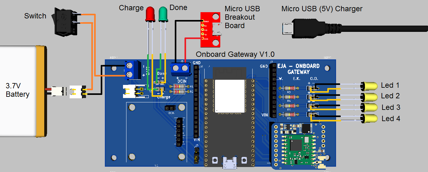
Wiring diagram for the Onboard Gateway v1.0.
User Interface
For more information about the GUI visit the following post.
Future Improvements
For more information about the recommended future improvements for the electronic design visit the following post.